
Method and system for controlling wellbore production temperature

a wellbore and production temperature technology, applied in the direction of wellbore/well accessories, fluid removal, insulation, etc., can solve the problems of significant wellbore stability issues, significant quantity of hydrocarbon, mineral or other resources has remained undeveloped, and the geological formation overlying the production zone is overheated, so as to reduce the fluid temperature and prevent the geological formation from overheating.

Active Publication Date: 2015-11-24
WORLD ENERGY SYST
View PDF8 Cites 0 Cited by
  • Summary
  • Abstract
  • Description
  • Claims
  • Application Information

AI Technical Summary

Benefits of technology

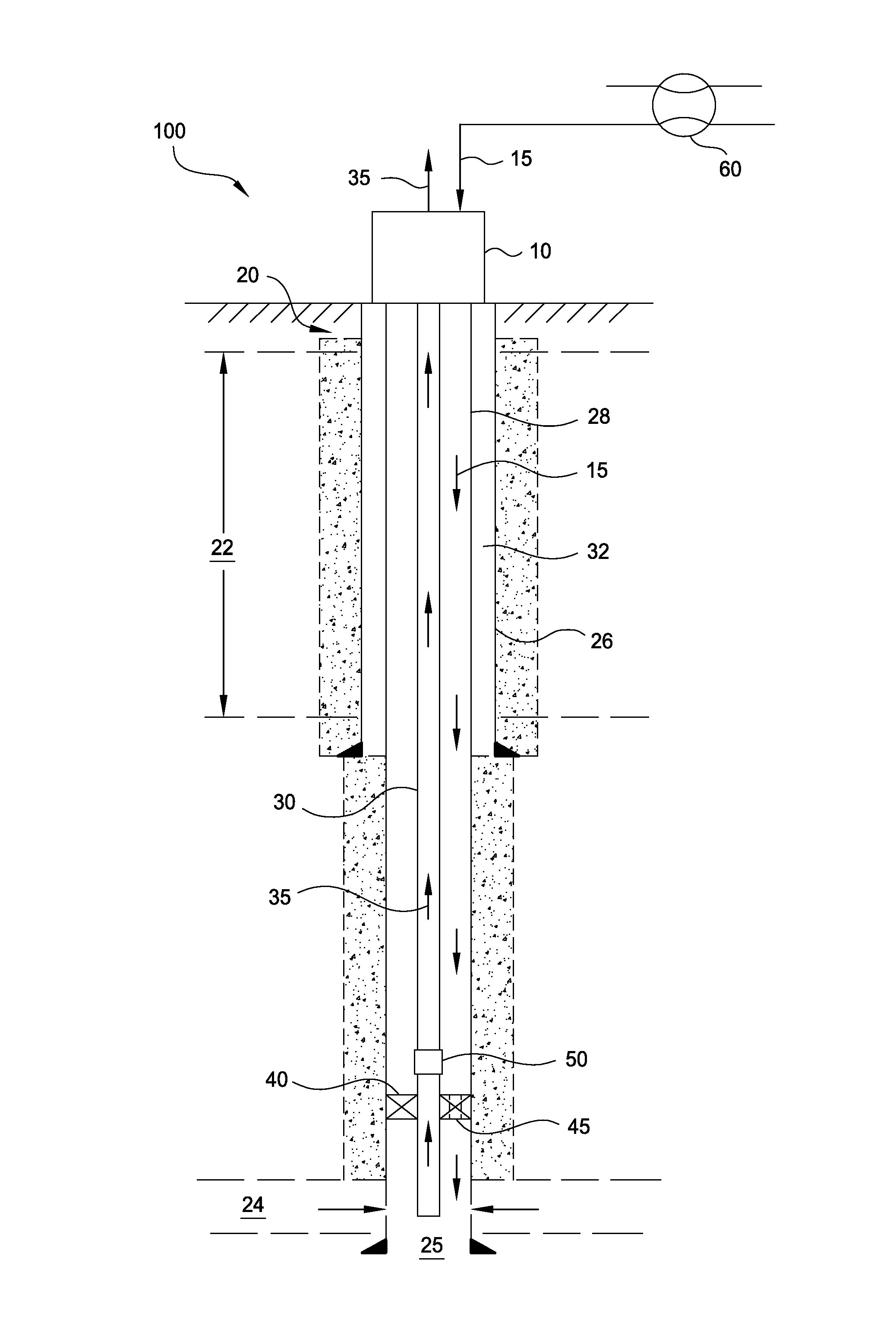
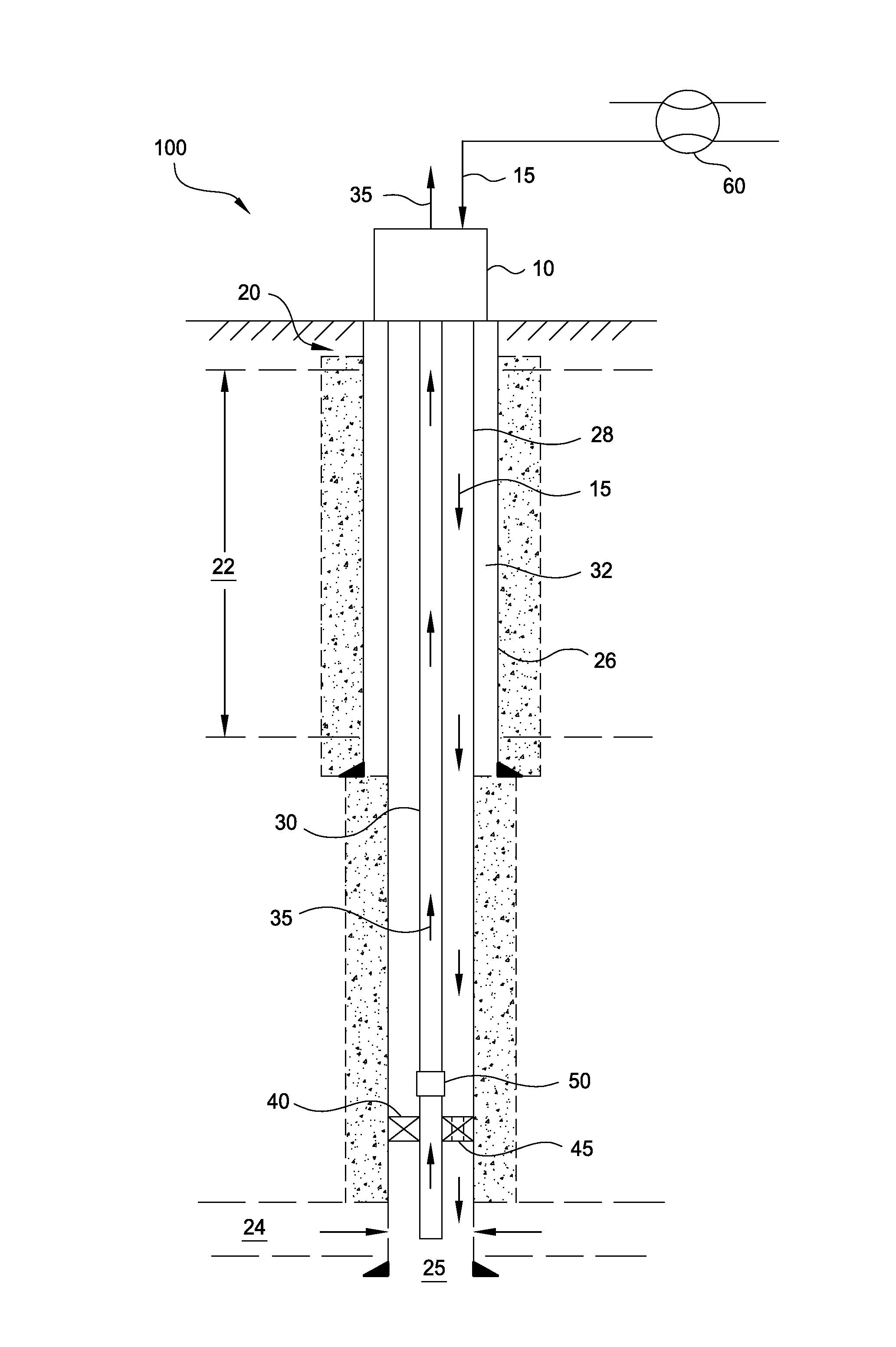
[0007]Embodiments of the invention include a method of controlling wellbore production temperature, comprising supplying a cooling fluid through an annulus formed between a production tubing and a production casing, wherein the production casing extends through a geological formation overlying a subsurface reservoir; producing fluid from the subsurface reservoir through the production tubing; and preventing overheating of the geological formation by using the cooling fluid to reduce a temperature of the fluid produced through the production tubing.

Problems solved by technology

There are situations where the produced fluids are so relatively hot that there is a danger of overheating the geologic formations overlying the production zone, such as a hydrate or a permafrost layer overlying a hydrocarbon reservoir.
Overheating of a permafrost layer may for example cause the permafrost to expand or thaw and thereby cause significant wellbore stability issues.
Disassociation of a hydrate zone may cause other problems as well.
As a result, a significant quantity of hydrocarbon, mineral or other resources have remained undeveloped because of a lack of enabling technology.
This is because current producing methods do not provide adequate temperature protection, control, and management.

Method used


Image

  • Method and system for controlling wellbore production temperature
  • Method and system for controlling wellbore production temperature

Examples


Embodiment Construction

[0011]Embodiments of the invention can be applied to any production well with a producing tubular string extending down through a cased wellbore. The producing tubular string may utilize a length of insulated tubing (vacuum insulated tubing or other design) installed, usually but not necessarily, in the upper section of the producing tubular string. A down flowing cooling fluid or fluids may be introduced into the wellbore annulus or annuluses at the top of the production well.

[0012]The wellbore production system operates by introducing the cooling fluid into a well annulus, and using heat exchange between the down flowing cooling stream and the up flowing production stream, as well as using heat exchange between the down flowing cooling stream and the adjacent geological formations, via heat transfer through the casing and cement. At the bottom of the well, the down flowing fluids are mixed with the net produced fluids, and the total fluids are directed up the tubular string. The w...


PUM


Abstract

A method and system of controlling the temperature of fluids produced from a reservoir to prevent overheating of an adjacent geological formation. A cooling fluid is supplied through an annulus formed between a production tubing and a production casing, which are in fluid communication with the reservoir. The cooling fluid is mixed with the reservoir fluid, and the fluids are produced through the production tubing. The temperature of the produced fluids is controlled or reduced by heat exchange with the cooling fluid supplied through the annulus to prevent excessive heat dissipation to the geological formation.

Description

BACKGROUND OF THE INVENTION[0001]1. Field of the Invention[0002]Embodiments of the invention relate to methods and systems for controlling and managing the production temperature of hydrocarbons and other fluids being produced through a wellbore designed to bring the fluids to the earth's surface from a subsurface producing zone or formation.[0003]2. Description of the Related Art[0004]It is common practice to drill one or more wellbores into the earth for the search and production of hydrocarbons and other similar fluids located in subsurface reservoirs. There are situations where the produced fluids are so relatively hot that there is a danger of overheating the geologic formations overlying the production zone, such as a hydrate or a permafrost layer overlying a hydrocarbon reservoir. Overheating of a permafrost layer may for example cause the permafrost to expand or thaw and thereby cause significant wellbore stability issues. Disassociation of a hydrate zone may cause other pro...

Claims


Application Information

Patent Timeline
Patent Type & Authority Patents(United States)
IPC IPC(8): E21B36/00
CPCE21B36/001E21B36/003
Inventor SCHNEIDER, MARVIN J.
Owner WORLD ENERGY SYST
Learn More