Pneumatic tire with tread having different curvature radii

a pneumatic tire and curvature radii technology, applied in the field of pneumatic tires, can solve the problems of increasing the radial growth of the center region, the uneven wear of the pneumatic tire, and the center region of the tread surface becoming prone to wear, so as to reduce the rolling resistance, improve fuel efficiency, and reduce the effect of rolling resistan

Active Publication Date: 2015-12-01
THE YOKOHAMA RUBBER CO LTD
View PDF29 Cites 0 Cited by
  • Summary
  • Abstract
  • Description
  • Claims
  • Application Information

AI Technical Summary

Benefits of technology

[0008]The present technology provides a pneumatic tire in which rolling resistance is reduced and wear resistance of the center region in the tread surface and wear resistance of the shoulder region can be enhanced.
[0010]According to this pneumatic tire, an amount of depression toward the tire radial direction inner side from the center portion arc to the shoulder side arc is reduced due to configuring an angle θ formed by a straight line joining the reference point and the center crown and a straight line parallel to the tire width direction and passing through the center crown to be in a range 0.025×β+1.0≦θ≦0.045×β+2.5. Furthermore, the arc of the tread surface from the center portion arc to the shoulder side arc is made closer to a straight line by configuring a relationship between a curvature radius Rc of the center portion arc and a curvature radius Rs of the shoulder side arc to be 12≦Rc / Rs≦30, and configuring a relationship between a reference developed width L that is an arc length of the center portion arc from the tire equatorial plane to a position at an edge of the shoulder side arc on the tire width direction inner side and a developed tread width TDW to be 0.2≦L / (TDW / 2)≦0.7. Therefore, radial growth of the center portion arc is suppressed and, as a result, wear of the shoulder region and wear of the center region of the tread surface can be improved. More specifically, wear of the center region can be improved while worsening of wear of the shoulder region is suppressed.
[0012]Shoulder wear can be more preferably suppressed by configuring TDW / SW to be not less than 0.65. Additionally, rolling resistance can be further reduced by configuring TDW / SW to be not more than 0.85. Therefore, according to this pneumatic tire, rolling resistance can be reduced, and prominent enhancements in wear resistance of the center region of the tread surface and wear resistance of the shoulder region can be obtained.
[0014]Shoulder wear can be more preferably suppressed by configuring the curvature radius SHR to be not less than 32 and center wear can be preferably suppressed by configuring the curvature radius SHR to be not more than 45. Therefore, according to this pneumatic tire, rolling resistance can be reduced, and prominent enhancements in wear resistance of the center region of the tread surface and wear resistance of the shoulder region can be obtained.
[0016]Applied air pressure is preferably increased to reduce rolling resistance in order to improve fuel efficiency. Thus, according to this pneumatic tire, by application to a high internal-pressure pneumatic tire for use on a passenger car, rolling resistance can be reduced, and prominent enhancements in wear resistance of the center region of the tread surface and wear resistance of the shoulder region can be obtained.
[0017]With the pneumatic tire according to the present technology, a pneumatic tire can be provided in which rolling resistance is reduced and wear resistance of the center region in the tread surface and wear resistance of the shoulder region can be enhanced.

Problems solved by technology

However, increasing the applied air pressure leads to an increase in radial growth of a center region (center in the tire width direction).
An increase in ground contact pressure of the center region accompanies the increase in radial growth thereof, which results in the center region of the tread surface becoming prone to wear.
However, when the pneumatic tire described in Japanese Unexamined Patent Application Publication No. 2008-307948 is highly pressurized, unevenness of wear of the pneumatic tire cannot be sufficiently suppressed.
Moreover, depending on the shape thereof, rolling resistance of the pneumatic tire cannot be appropriately reduced.

Method used


Image

  • Pneumatic tire with tread having different curvature radii
  • Pneumatic tire with tread having different curvature radii
  • Pneumatic tire with tread having different curvature radii

Examples


examples

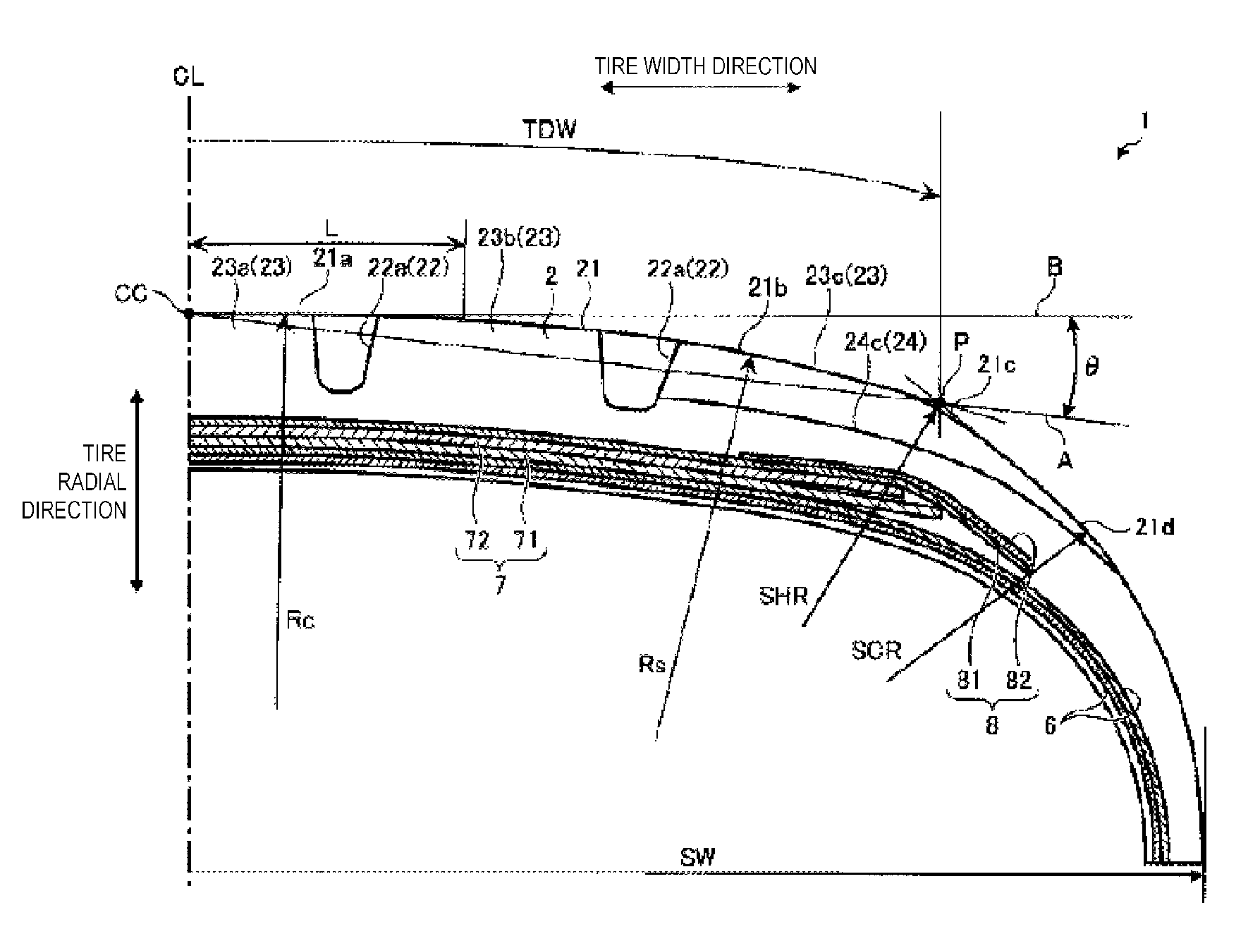
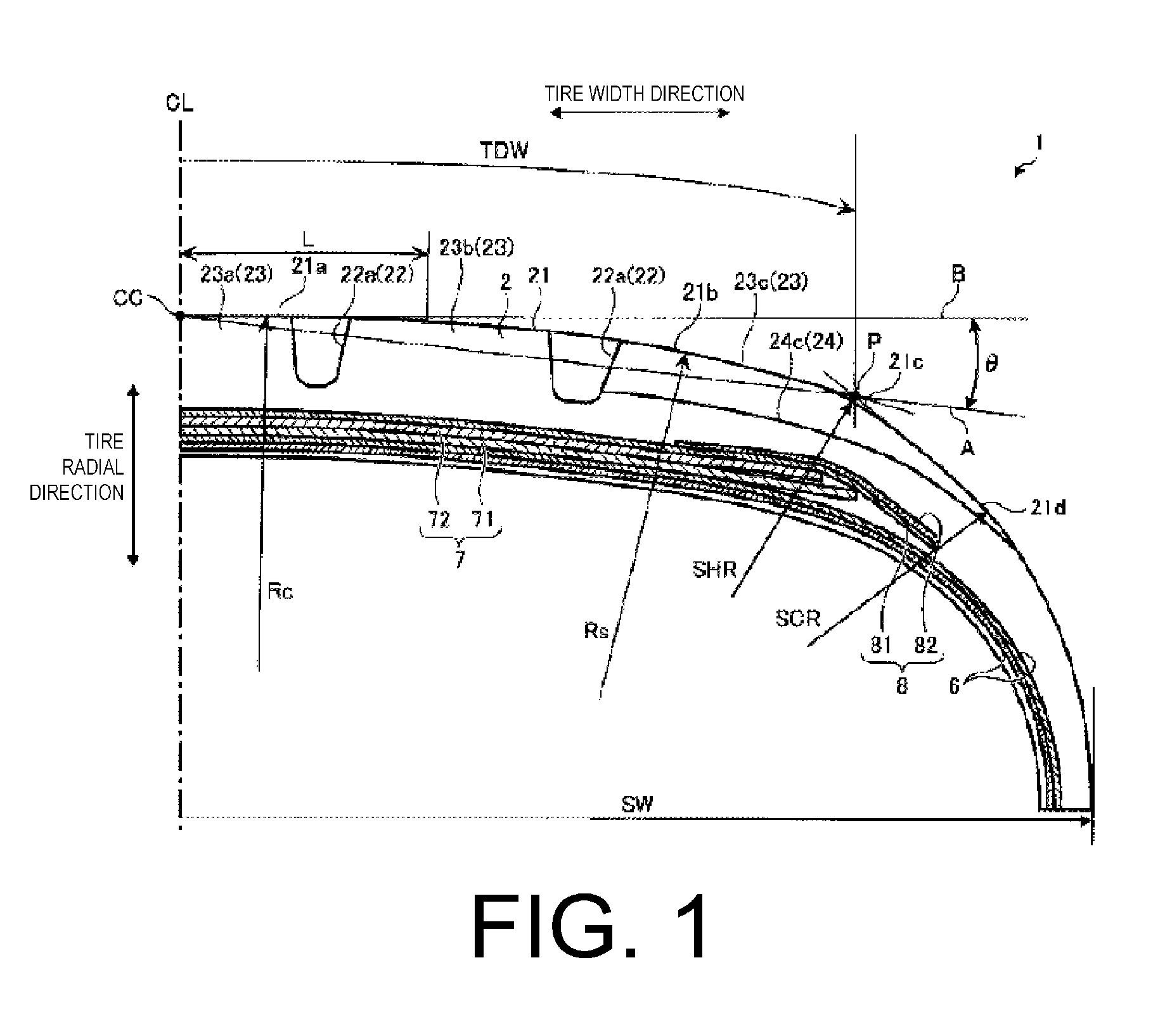
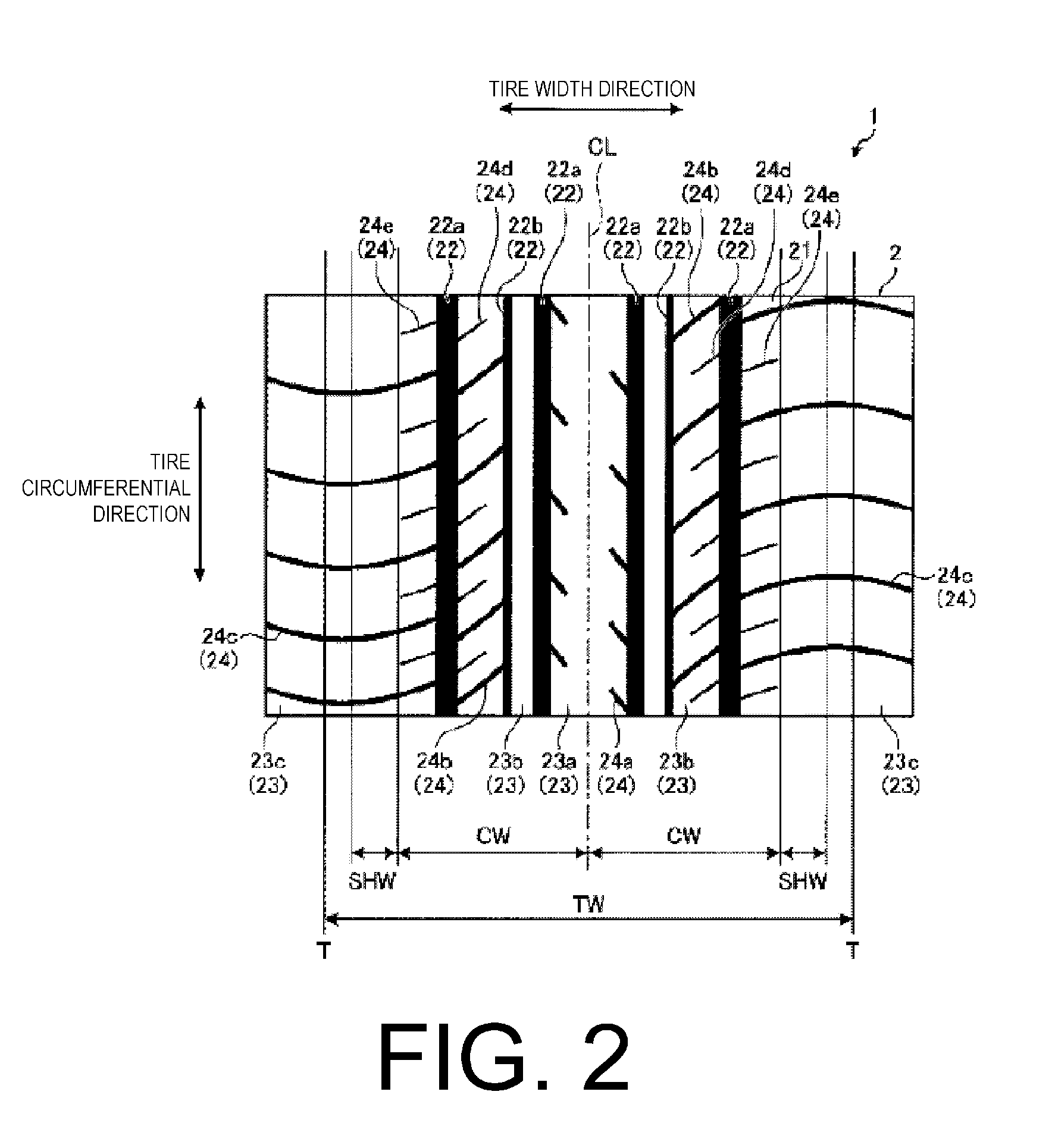
[0056]In the examples, performance tests for tire performances (center wear, shoulder wear, and rolling resistance) were performed on a plurality of types of pneumatic tires under different conditions (see FIGS. 3 to 8).

[0057]Of these performance tests, in Conventional Examples 1 and 2, Working Examples 1 to 12 and 17 to 28, and Comparative Examples 1 to 6 shown in FIGS. 3 to 5, 7, and 8, a pneumatic tire having a tire size of 215 / 55R17 was assembled on a rim of a 17×7J aluminum wheel, inflated to an air pressure specified for each example, and mounted on a test vehicle (3 L front-engine rear-drive (FR) sedan). The pneumatic tires used in the performance tests had an aspect ratio of 55. Therefore, a range of θ was 2.375≦θ≦4.975, and a preferable range was 2.85≦θ≦4.5. Of these performance tests, in Conventional Examples 3 and 4, Working Examples 13 to 16, and Comparative Examples 7 and 8 shown in FIG. 6, a pneumatic tire having a tire size of 245 / 35ZR19 was assembled on a rim of a 19...


PUM


Abstract

An intersection of an extended line of a shoulder side arc and an extended line of a side portion arc is a reference point P, an aspect ratio is β, and an angle θ formed by a straight line A joining the reference point P and a center crown CC and a straight line B in a tire width direction that passes through the center crown CC is configured such that 0.025×β+1.0≦θ≦0.045×β+2.5. A curvature radius Rc of a center portion arc and a curvature radius Rs of the shoulder side arc are configured such that 12≦Rc / Rs≦30. A reference developed width L from a tire equatorial plane CL to an edge of the shoulder side arc on a tire width direction inner side and a developed tread width TDW are configured such that 0.2≦L / (TDW / 2)≦0.7.

Description

PRIORITY CLAIM[0001]Priority is claimed to Japan Patent Application Serial No. 2010-242367 filed on Oct. 28, 2010.BACKGROUND[0002]1. Technical Field[0003]The present technology relates to a pneumatic tire, and particularly relates to a pneumatic tire in which, when applied air pressure is increased to reduce rolling resistance for the purpose of improving fuel efficiency, wear in a center region and worsening of dry braking ability caused by an increase in ground contact pressure that accompanies an increase in radial growth of the center region are improved.[0004]2. Related Art[0005]Conventionally, pneumatic tires are known in which a curvature of a profile along a tire width direction of a tread surface is close to a straight line (e.g. see Japanese Unexamined Patent Application Publication No. 2008-307948). Such a pneumatic tire has a plurality of arcs having different curvature radii in a tread surface, including at least a center portion arc positioned in a center in the tire w...

Claims


Application Information

Patent Timeline
Patent Type & Authority Patents(United States)
IPC IPC(8): B60C11/00B60C11/03
CPCB60C11/0083B60C11/0306Y02T10/86
Inventor KUBOTA, MASATAKA
Owner THE YOKOHAMA RUBBER CO LTD
Why Eureka
Try Eureka