Rod-bed assembly

a technology of rod-bed assembly and rod-bed body, which is applied in the direction of coatings, machine supports, and applied substance rearrangement, can solve the problems of unsuitable rod-bed assemblies, and achieve the effects of preventing contamination, low thermal conductivity, and thermal durability

Active Publication Date: 2015-12-08
VALMET TECH INC
View PDF12 Cites 0 Cited by
  • Summary
  • Abstract
  • Description
  • Claims
  • Application Information

AI Technical Summary

Benefits of technology

[0017]Another object of the present invention is to create a rod-bed assembly with simple and fast replacement for the rod and for the insert / rod-bed from the holder as these are wearing parts that need to be replaced at regular intervals.
[0022]Advantageously the cross-section of the insert is of substantially even material thickness with the exception of at least one drawdown of decreased thickness for providing elasticity for inserting and removing the insert into and from the holder.
[0030]In the rod-bed assembly the holder is advantageously composite material for providing structural strength, mounting of the rod, holding of the rod, preventing the contamination due to advantageous tight formfitting fit with the insert, holding lubrication water in the water channels, low thermal conductivity and due to its rigidity provides for the possibility of light, low-cost and elastic insert. Further advantages of a composite holder are the thermal durability in process temperatures of coating and sizing, for example over 80° C.
[0031]In the rod-bed assembly the insert is advantageously of elastic material, preferably plastic material, more advantageously of polyethene providing good friction properties, sufficient thermal properties, and cost-effectiveness due to protecting the holder from wear, easy inserting and removing, and good formfitting.

Problems solved by technology

It is a problem of prior art that the rod-bed assemblies are not suitable in cases where rods of diameter over 25 mm are used since space requirements for inserts of rod-bed assemblies that would be suitable for larger rods (i.e. rods with diameter over 25 mm) cannot be realized due to lacking space for locking surfaces, cavities etc. of these known assemblies.

Method used


Image

  • Rod-bed assembly
  • Rod-bed assembly
  • Rod-bed assembly

Examples


Embodiment Construction

[0038]In the following description relating to the figures, the same reference signs are used for corresponding parts and part components unless otherwise mentioned.

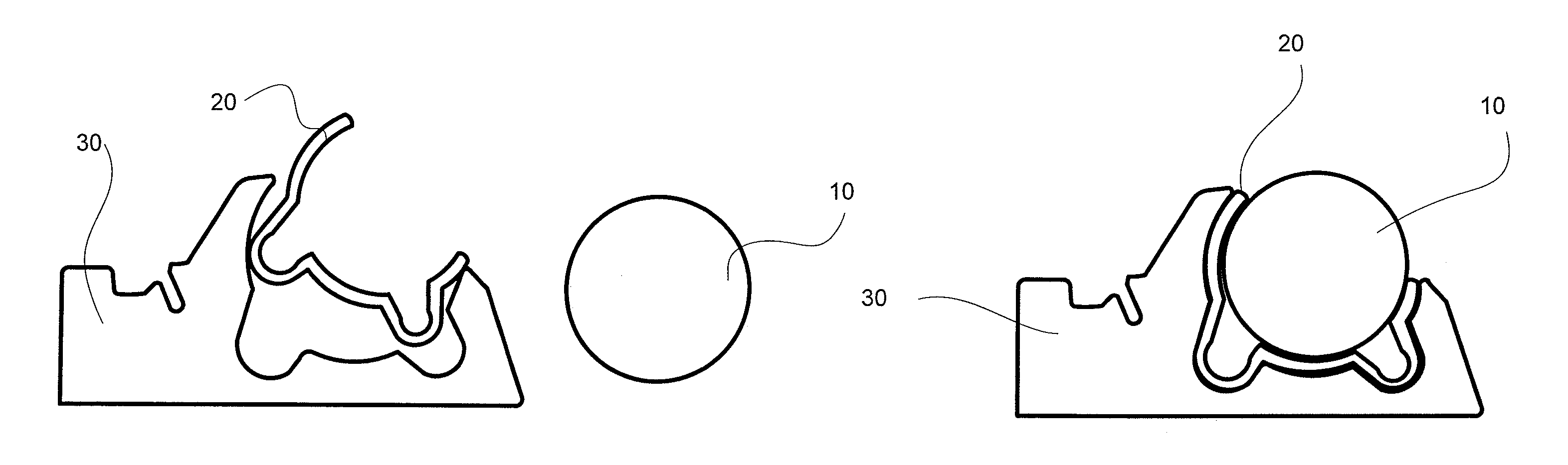
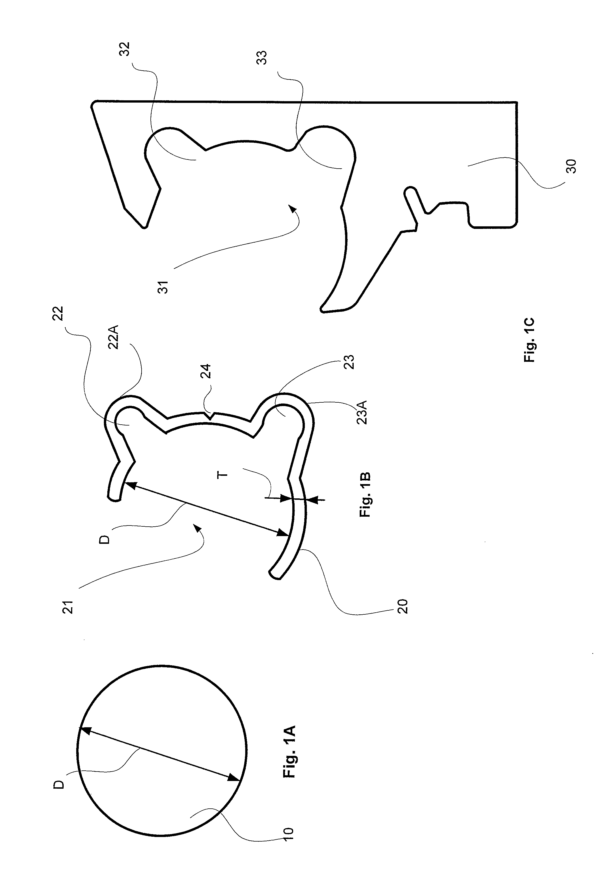
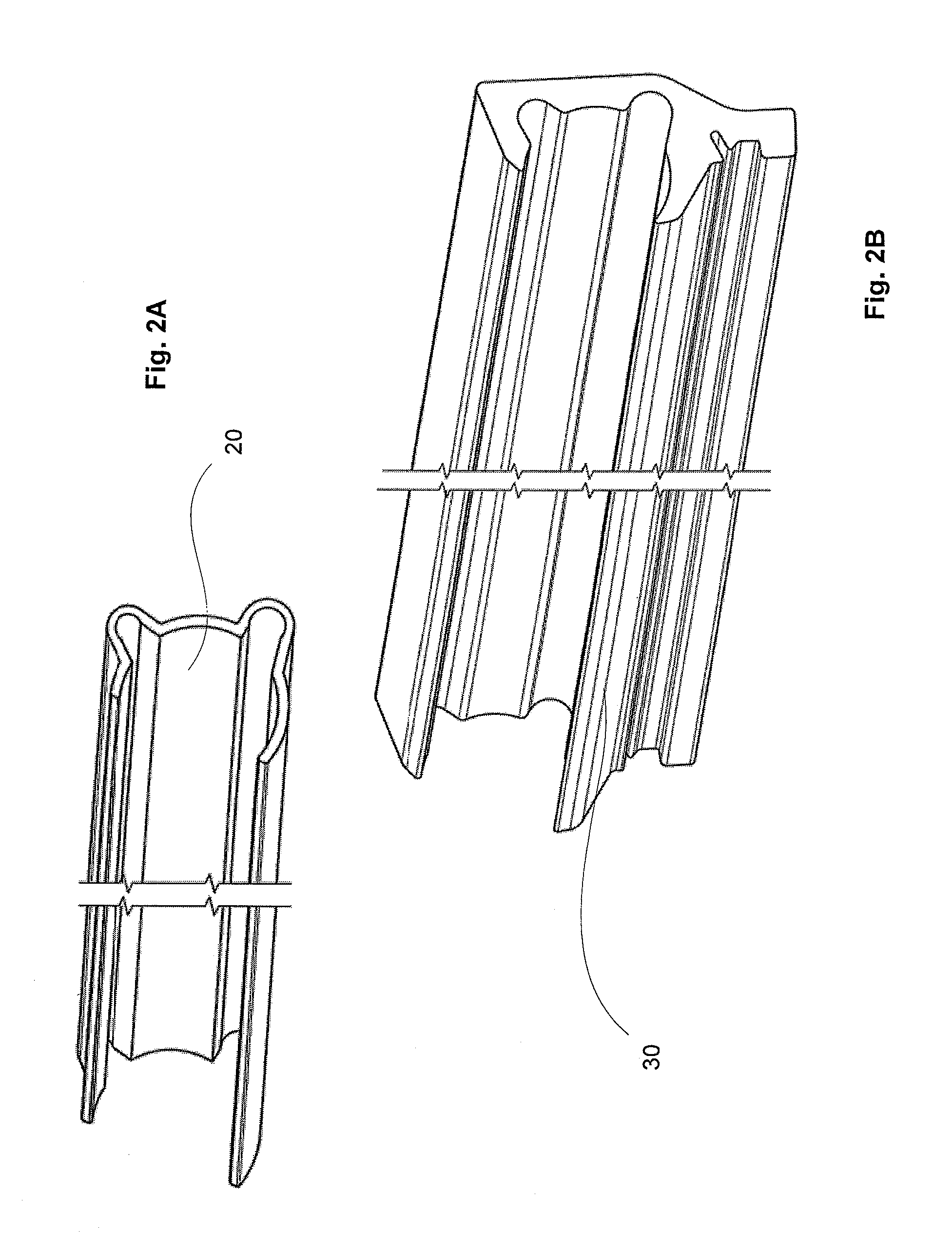
[0039]In FIG. 1A is schematically shown a cross section of a rod 10 for dosing of coating medium onto the fiber web during coating of the fiber web in a coater or for dosing of sizing medium onto the sizing roll, by which the sizing medium is applied onto the fiber web, during sizing at a sizer. The rod 10 is advantageously of metal and its diameter D is over 25 mm, for example 35 mm or 40 mm. The rod 10 is in this example smooth surfaced but the rod-bed assembly according to the invention is also suitable for grooved rods. The rod 10 will be placed into a recess 21 of an insert 20, shown in FIG. 1B, located in a holder 30, shown in FIG. 1C for its use, advantageously inserted in the radial direction of the rod 10 from the front side of the insert and the holder.

[0040]In FIG. 1B is schematically shown an insert 20 of the...


PUM


Abstract

A rod-bed assembly has a holder (30) with a groove (31) into which an insert (20) is removably and insertably supported. The assembly has a rod (10) which is rotatably supported in a recess (21) on the front side of the insert (20). The material thickness (T) of the cross-section of the insert (20) is between 1-5 mm. The invention also relates to a rod -rod-bed assembly.

Description

CROSS REFERENCES TO RELATED APPLICATIONS[0001]This application claims priority on European Application No. EP12186205, filed Sep. 27, 2012, the disclosure of which is incorporated by reference herein.STATEMENT AS TO RIGHTS TO INVENTIONS MADE UNDER FEDERALLY SPONSORED RESEARCH AND DEVELOPMENT[0002]Not applicable.BACKGROUND OF THE INVENTION[0003]The present invention relates to a rod-bed assembly and to be more precise to a rod-bed assembly for a rod of a device for coating or sizing a fiber web, particularly a paper or a board web. The invention also relates to a rod—rod-bed assembly.[0004]In this description and in the claims, by term rod-bed assembly is meant the rod-bed comprising an insert and a holder for a rod of a device for coating or sizing a fiber web. The front side of a rod-bed assembly is the side on which the rod is located in use i.e. the side that will face the fiber web to be coated or the sizing roll onto which the sizing agent is applied by the rod when sized. It s...

Claims


Application Information

Patent Timeline
Patent Type & Authority Patents(United States)
IPC IPC(8): B05C11/00F16M13/02B05C11/02D21H25/12B05C1/08
CPCB05C11/00B05C1/0834B05C11/025D21H25/12F16M13/02
Inventor LINTULA, TIMO S.KARUSALMI, ARTOKAUTTO, ARI-PEKKAKUPARINEN, SAMI
Owner VALMET TECH INC
Why Eureka
Try Eureka