Apparatus having a closed-off work chamber with improved cleanability

a technology of work chamber and closed-off work chamber, which is applied in the direction of ventilation systems, heating types, and domestic stoves or ranges. it can solve the problems of return air conduit cleaning, insufficient cleaning of isolator, and inability to reach the internal regions of spray devices, etc., to achieve safe and effective cleaning, simple and fast replacement of membranes, and quick and simple cleaning.

Inactive Publication Date: 2010-03-25
ROBERT BOSCH GMBH
View PDF10 Cites 1 Cited by
  • Summary
  • Abstract
  • Description
  • Claims
  • Application Information

AI Technical Summary

Benefits of technology

[0006]The apparatus of the invention has the advantage over the prior art that safe and effective cleaning of both the apparatus and a return air conduit is possible. In the apparatus of the invention, there is not the danger that additional parts or the closed-off inner chamber will become contaminated. This is attained according to the invention in that at least one additional connecting point between a closed-off work chamber of the apparatus and a return air conduit is provided, which is closed by means of a blocking device. When cleaning of the apparatus is necessary, the blocking device is opened, and the return air conduit can be cleaned by passing a cleaning element through the opened connecting point. It should be noted that the connecting point according to the invention is provided in addition to an outlet opening in the work chamber, by way of which opening a constant communication of the work chamber with the return air conduit for assuring the flow through the work chamber during the use of the work chamber is possible. Thus according to the invention, the return air conduit as well can be cleaned quickly and simply as needed, so that there is no danger that an ensuing work step will be contaminated with particles from the return air conduit.
[0007]Especially preferably, the blocking device includes a membrane which is destroyed for cleaning of the return air conduit. In other words, the membrane is for instance pierced by the cleaning element and damaged, so that the cleaning element can be introduced into the return air conduit via the connecting point. The destruction of the membrane has the advantage in particular that a worker who has to perform the cleaning is visually shown that, if the membrane is destroyed, he has already performed the cleaning. As the membrane, a thin metal membrane is especially preferably used. Before the next work step, the destroyed membrane is then replaced, after the apparatus is cleaned, with an intact membrane.
[0008]To enable simple, fast replacement of a destroyed membrane with an intact membrane, a bayonet mount is preferably provided, and the membrane is preferably fixed by being clamped in place.
[0009]In an alternative feature of the present invention, the blocking device includes a membrane which has at least one slit. For cleaning the return air conduit, the cleaning element is introduced through the slit in the membrane, without destroying the membrane in the process. Once again, safe and effective cleaning of the return air conduit can be obtained as a result. It is especially advantageous that the membrane that has the slits does not have to be replaced. However, in that case the worker is also not informed whether he has already cleaned the return air conduit in this region, since after the cleaning element is withdrawn, the membrane returns to its original outset state. The slit membrane preferably has a cross-shaped slit and is made from a rubber material.
[0010]In another alternative feature of the present invention the blocking device is disposed detachably at the connecting point to the return air conduit. As a result, once again a blocking device is furnished which need not be destroyed for cleaning. To clean the return air conduit, the blocking device must merely be detached from the connecting point. This can be done for instance by the provision of a blocking device in the form of a cap which can for instance be unhooked from a closed position. Alternatively, the blocking device can be opened by rotating or pulling it or the like. To prevent the caplike blocking device from being lost, the caplike blocking device is preferably joined to a wall of the work chamber preferably by means of a connecting element, in particular a cord or chain or hinge. As a result, the caplike blocking device hangs securely on the wall of the work chamber and cannot be lost in a cleaning operation. Another advantage of the caplike blocking device that can be named is that this provides visual monitoring for a worker as to whether this portion of the return air conduit has already been cleaned, or not.
[0011]Preferably, the cleaning element is a spray gun with a preferably long rifle-like barrel. Also preferably, a mandrel or the like is disposed on the free end of the cleaning element, to make it simple to pierce the membrane or punch it open.

Problems solved by technology

However, a problematic aspect is particularly the cleaning of the return air conduit, since the return air conduit communicates with the closed-off work chamber of the apparatus only via an outlet opening.
It has been found that the decontamination of the isolator that must be done after cleaning and is understood also to have to be done in the return air conduit is often inadequate to reach internal regions of the spray devices.
It can therefore happen that some of the toxic medium is still present in the spray devices in the return air conduit, so that it is possible for a subsequent batch to be contaminated or for the worker to be contaminated during servicing tasks.
However, that would mean that the return air conduit has to be opened, which can be done only under conditions of full protection for the worker, to avoid contaminating the worker with poisonous substances.
Another disadvantage is that the closed-off apparatus is opened into a space with a lower classification, so that the possibility exists that the apparatus will be contaminated.

Method used


Image

  • Apparatus having a closed-off work chamber with improved cleanability
  • Apparatus having a closed-off work chamber with improved cleanability

Examples


Embodiment Construction

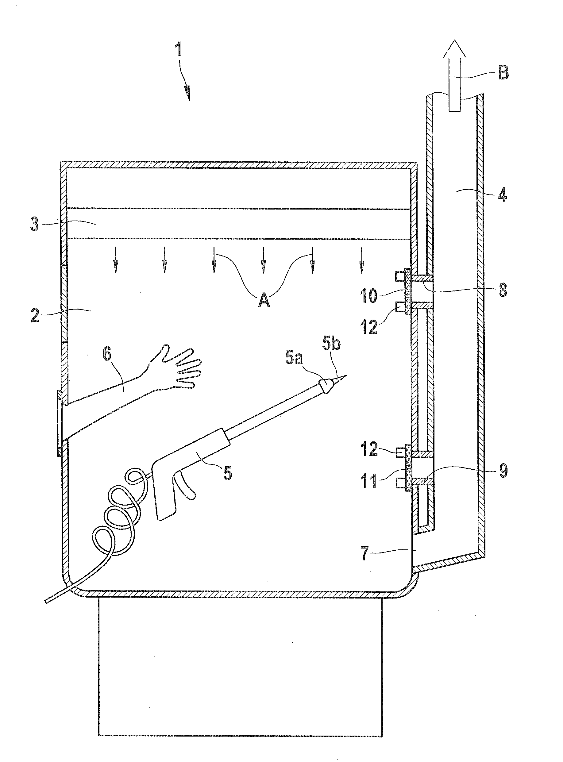
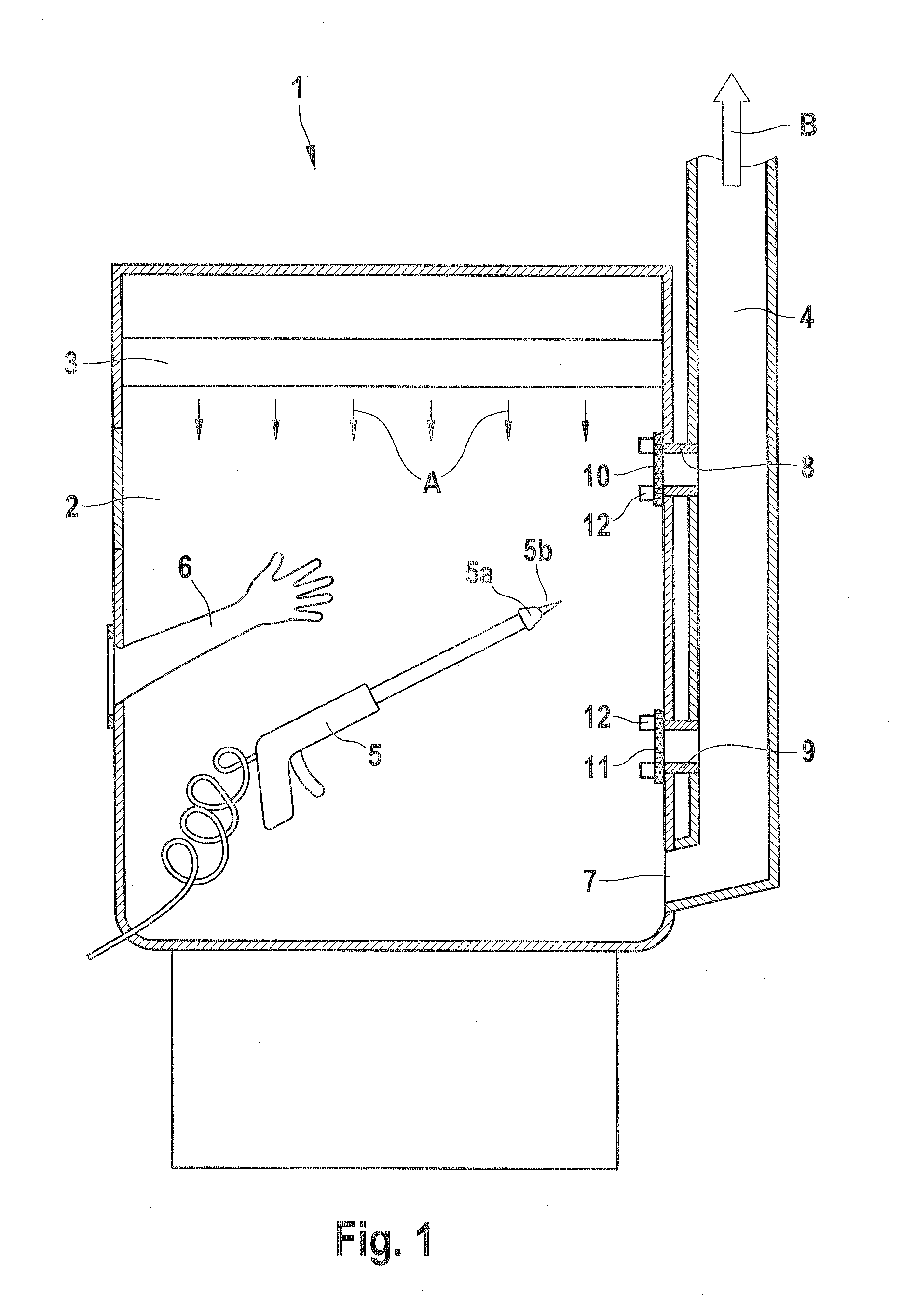
[0015]Below, in conjunction with FIG. 1, an apparatus (isolator) with a closed-off work chamber 2 will be described in detail.

[0016]As can be seen from FIG. 1, the apparatus 1 includes a closed-off work chamber 2, in which a toxic medium, for instance, is put into containers. The apparatus 1 includes a ventilating device 3, which assures that a particle-free laminar air stream is passed through the work chamber 2. This is indicated in FIG. 1 by the small arrows A. The apparatus 1 further includes a return air conduit 4, which communicates with the work chamber 2 via an outlet opening 7. Via the outlet opening 7, the air flows out of the work chamber 2 into the return air conduit 4 and from there, via a filter, not shown, it flows back out of the apparatus 1 again. This is indicated in FIG. 1 by the arrow B.

[0017]The apparatus 1 further includes a spray gun 5, which serves to clean both the work chamber 2 and the return air conduit 4. The spray gun 5 is operated from outside the appa...


PUM


Abstract

The invention relates to an apparatus, in particular for processing toxic and/or medical media, including a closed-off work chamber, in which the medium can be manipulated. A ventilating device delivers a particle-free or laminar or turbulent air stream to the work chamber. A return air conduit communicates with the work chamber via an outlet opening and by way of which air is carried away from the work chamber. A cleaning element is disposed in the work chamber, to enable cleaning of the work chamber and of the return air conduit. At least one blocking device blocks off an additional connecting portion between the work chamber and the return air conduit. The blocking device is able to be opened for cleaning of the return air conduit.

Description

CROSS-REFERENCE TO RELATED APPLICATION[0001]This application is based on German Patent Application 10 2008 041 521.9 filed Aug. 25, 2008.BACKGROUND OF THE INVENTION[0002]1. Field of the Invention[0003]The present invention relates to an apparatus having a closed-off work chamber, in particular for processing toxic media.[0004]2. Description of the Prior Art[0005]An apparatus with a closed-off work chamber is known from the prior art, as an “isolator” among other things. Such devices are used particularly in medical technology for putting medications in containers. Such devices are thoroughly rinsed with a particle-free or laminar or turbulent air stream, so that the medications or other media can be processed particle-free. For returning the introduced air stream, a return air conduit is typically used, on the end of which a filter is disposed. After a batch of the medium has been put in containers, the apparatus must typically be cleaned from the inside. For that purpose, it is kno...

Claims


Application Information

Patent Timeline
Patent Type & Authority Applications(United States)
IPC IPC(8): B08B15/02
CPCF24F7/10F24F2221/225F24F3/1607B08B15/026F24F13/029B08B3/026F24F3/161F24F3/163F24F3/167
Inventor HERTFELDER, THOMASSIPPEL, BERNHARDMACK, THOMASDAEUBER, ROLF
Owner ROBERT BOSCH GMBH
Why Eureka
Try Eureka