System and method for detecting spall initiation and defining end of life in engine components

a technology of end of life and engine components, applied in the field of health monitoring, can solve the problems of reducing the reliability of the engine, affecting the mission, and affecting the accuracy of the end of life indication, so as to reduce the downtime of the vehicle, increase the size, and high confidence level

Active Publication Date: 2015-12-08
HONEYWELL INT INC
View PDF26 Cites 6 Cited by
  • Summary
  • Abstract
  • Description
  • Claims
  • Application Information

AI Technical Summary

Problems solved by technology

The technical challenge is that while the incubation phase of a spall could last several tens of hours, the steady growth and rapid growth phases of a spall last in the order of hours and minutes respectively.
Also, the transition to rapid growth typically occurs roughly when the spall spans two rolling elements, but this is not precise, and can result in the end of life indication coming too close to functional failure.
An indicator based solely on the debris mass could jeopardize the mission in cases where the fault does not progress like a typical inner race spall.

Method used


Image

  • System and method for detecting spall initiation and defining end of life in engine components
  • System and method for detecting spall initiation and defining end of life in engine components
  • System and method for detecting spall initiation and defining end of life in engine components

Examples


Embodiment Construction

[0011]The following detailed description is merely exemplary in nature and is not intended to limit the invention or the application and uses of the invention. As used herein, the word “exemplary” means “serving as an example, instance, or illustration.” Thus, any embodiment described herein as “exemplary” is not necessarily to be construed as preferred or advantageous over other embodiments. All of the embodiments described herein are exemplary embodiments provided to enable persons skilled in the art to make or use the invention and not to limit the scope of the invention which is defined by the claims. Furthermore, there is no intention to be bound by any expressed or implied theory presented in the preceding technical field, background, brief summary, or the following detailed description.

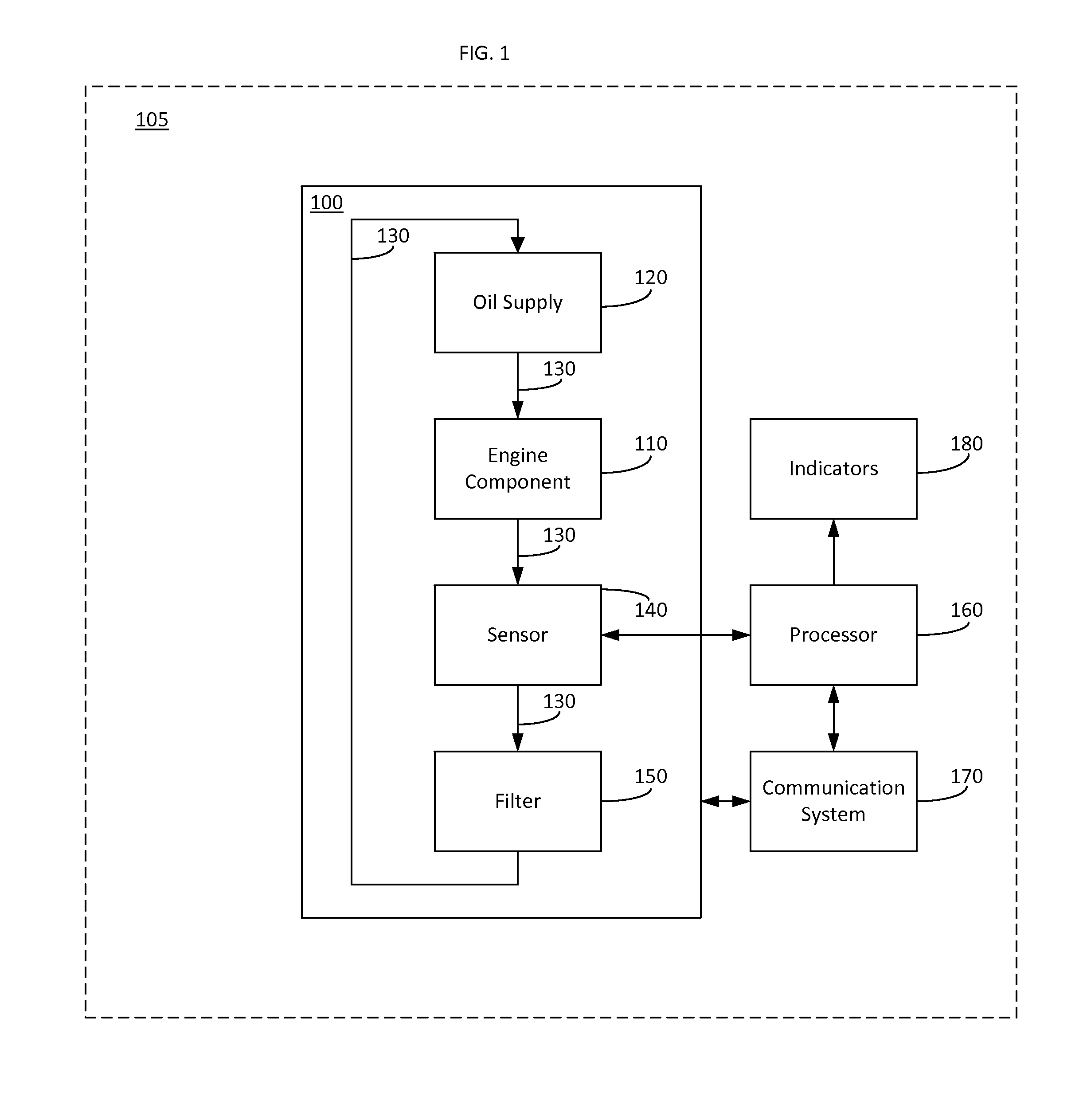
[0012]FIG. 1 is a block diagram of an engine 100, in accordance with an embodiment. The engine 100 may be an engine for a vehicle, such as an aircraft, a spacecraft, an automobile, or a marine ...


PUM

PropertyMeasurementUnit
sizeaaaaaaaaaa
mass rate constantaaaaaaaaaa
timeaaaaaaaaaa

Abstract

A system and method are provided for detecting a spall in an engine. The vehicle, for example, may include, but is not limited to an engine, an oil debris sensor coupled to the engine, a communications system, and a processor communicatively coupled to the oil debris sensor and the communications system. The processor may be configured to increment a counter when the oil debris sensor detects a particle over a predetermined size, increment the counter when a mass of a plurality of particles under the predetermined size exceeds a predetermined mass threshold, transmit, via the communications system, a first message when the counter exceeds a predetermined counter threshold, and reset the counter after predetermined amount of time.

Description

CROSS-REFERENCE TO RELATED APPLICATION(S)[0001]This application claims the benefit of U.S. provisional patent application Ser. No. 61 / 656,814, filed Jun. 7, 2012.TECHNICAL FIELD[0002]The present disclosure generally relates to health monitoring, and more particularly relates to a system and method for detecting spall initiation and defining end of life.BACKGROUND[0003]A mechanical health monitoring system for rotating machinery has to two primary objectives. One primary objective is issuing an advance warning of an impending failure. The other primary objective is preventing mission aborts and costly repairs due to primary and secondary damage. The advance warning period mentioned in the first objective can be extended by either detecting a spall early and with high confidence or by delaying the end of life as late as possible. The current practice is based on the manual inspection of an electronic chip detector and interpretation of the debris observed via human eye. The assessment...

Claims


Application Information

Patent Timeline
Patent Type & Authority Patents(United States)
IPC IPC(8): G06F19/00F16N29/00B60W50/00G01N33/28
CPCB60W50/00F16N29/00F16N2250/32G01N33/2858F16N2200/04
Inventor ULUYOL, ONDERHICKENBOTTOM, CHRIS
Owner HONEYWELL INT INC
Why Eureka
Try Eureka