

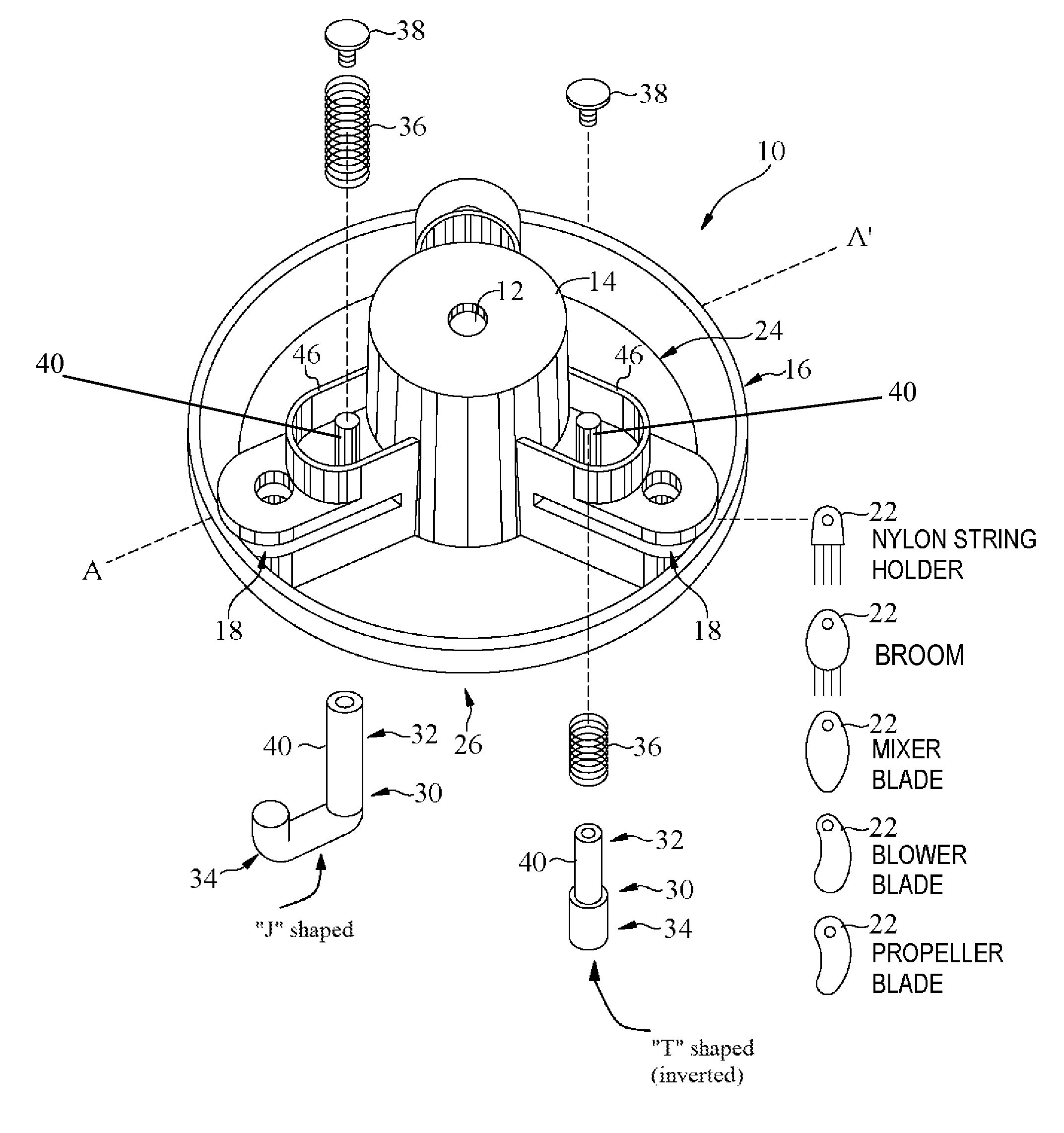
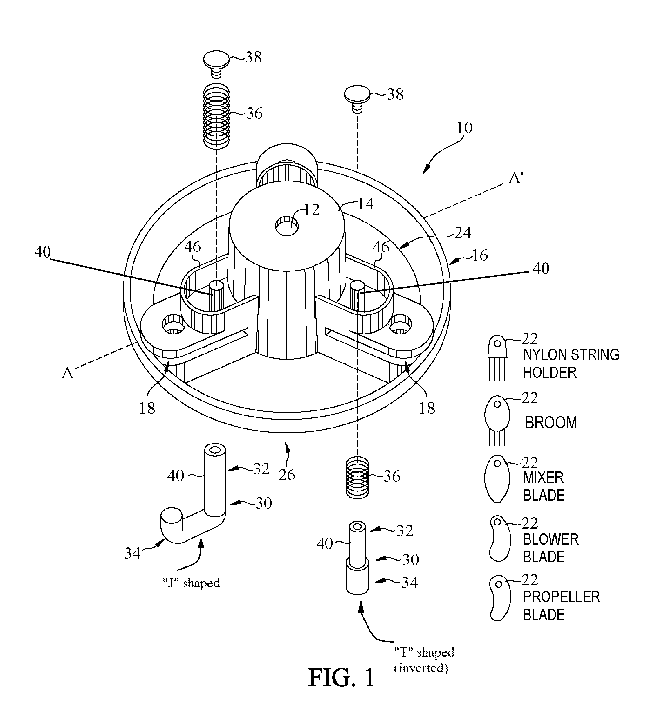
Rotary trimmer apparatus and related rotary head assembly
a rotary trimmer and head assembly technology, applied in metal-working apparatus, agricultural tools and machines, agriculture, etc., can solve the problems of requiring extensive time to change, certain drawbacks of the trimmer apparatus, etc., and achieves convenient removal quick and easy insertion of the trimmer line, and simple and efficient trimming.
- Summary
- Abstract
- Description
- Claims
- Application Information
AI Technical Summary
Benefits of technology
Problems solved by technology
Method used
Image

Examples
Embodiment Construction
[0018]Illustrative implementations of the invention are described below as they might be employed in the construction and use of a rotary trimmer apparatus and related method according to at least one implementation of the present invention. It will be of course appreciated that in the development of such an actual implementation, numerous implementation-specific decisions must be made to achieve the developers' specific goals, such as compliance with system-related and business-related constraints, which will vary from one implementation to another. Moreover, it will be appreciated that such a development effort might be complex and time-consuming, but would nevertheless be a routine undertaking for those of ordinary skill in the art having the benefit of this disclosure. In the detailed description below, general discussion of alternative steps, configurations, features and / or components may employ reference to numbered components identified in the accompanying figures. However, i...
PUM
| Property | Measurement | Unit |
|---|---|---|
| diameter | aaaaa | aaaaa |
| external force | aaaaa | aaaaa |
| length | aaaaa | aaaaa |
Abstract
Description
Claims
Application Information