Vibration damping system for a rolling mill with first and second passive hydraulic elements

a technology of passive hydraulic elements and vibration damping system, which is applied in the direction of metal rolling, mechanical equipment, and control devices of rolling mills. it can solve the problems of temporary breakage of lubrication film, limited force distribution, and inconvenient conditions

Active Publication Date: 2015-12-15
DANIELI & C OFF MEC SPA
View PDF3 Cites 2 Cited by
  • Summary
  • Abstract
  • Description
  • Claims
  • Application Information

AI Technical Summary

Benefits of technology

[0067]Another object of the present invention is to provide a rolling mill capable of working at rolling speeds close to the design speeds, without presenting the phenomena of chatter.

Problems solved by technology

This arrangement is limited in terms of the forces that can be applied for the elastic deformation of said cylinders.
These forces may be generated by the following effects:The tape itself, due to its intrinsic variations in thickness or hardness;Variations in the friction of the roller space, especially when it reaches maximum speeds, with the risk of even temporary breakage of the lubrication film;Defects induced in the rollers during adjustment operations;Unsuitable conditions of the cage mechanics, such as wear, play between the various components and damaged antifriction bearings.The simultaneous rolling of hard material accompanied by a marked reduction in thickness and a high rolling speed.
Such phenomena are manifested in a movement of the rollers, in the direction transverse to the rolling direction, i.e. they occur in the vertical direction and can reach uncontrollable amplitudes that are not suited to the rolling process.
Such phenomena are termed chatter and can create surface defects such as light / dark markings on the tape or variations in thickness that lead to the rejection of the rolled tape, whereby the defects depend on the mode of vibration of the cage.
Chatter is therefore a significant problem for the operation of rolling mills, because in addition to causing the rejection of the product, it significantly reduces production capacity.
Such systems permit the minimization of quality rejections, but do not resolve the problem related to the reduction of production capacity of the rolling mill.
Such a solution is not satisfactory because, on varying the dimensions of the rollers used in the rolling mill, the natural frequency also varies, even if slightly, and this also leads to the intervention on the anti-resonance system.
In addition, the contribution of the anti-resonance system leads to the emergence of two new resonance frequencies, with the risk that the chattering phenomenon will also begin.
The disadvantage of such a system is that it is positioned at the top of the cage and is therefore very distant from the rollers that act directly on the rollers during rolling.
In addition, JP08247211 does not describe the type of actuator, and does not give sufficient information for the concrete implementation of the damping system.
JP09174122 describes a damping system based on the insertion of hydraulic dampers between the fittings of the upper and lower rollers, but this solution is limited due to the limited capacity of the dampers to follow high-frequency vibrations.
In addition, said dampers have a negative effect on the rolling tolerances in the absence of the chatter phenomenon.

Method used


Image

  • Vibration damping system for a rolling mill with first and second passive hydraulic elements
  • Vibration damping system for a rolling mill with first and second passive hydraulic elements
  • Vibration damping system for a rolling mill with first and second passive hydraulic elements

Examples


Embodiment Construction

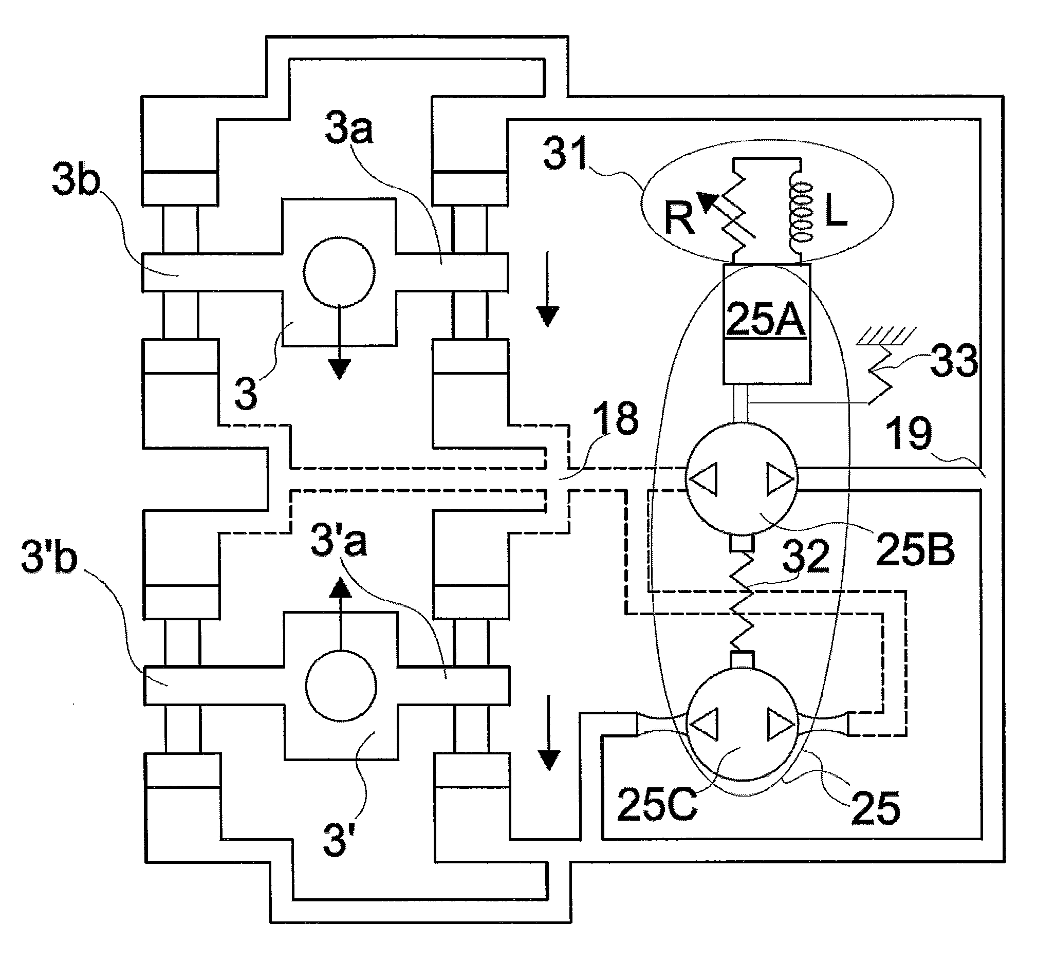
[0079]With reference to FIG. 4, we schematically show a system for controlling the flatness through the controlled bending of the working cylinders (bending) of the E-block type, showing the hydraulic circuits that determine the movement of the cylinders to which the present invention is applied. In particular, the dotted lines show the actuation circuits of a negative bending, i.e. that leads to a mutual approaching of the rollers to each other. The solid lines show the actuation circuits of a positive bending, i.e. that leads to a mutual distancing of the rollers from each other. The two opposing support blocks hold the fittings of two rollers on the same side.

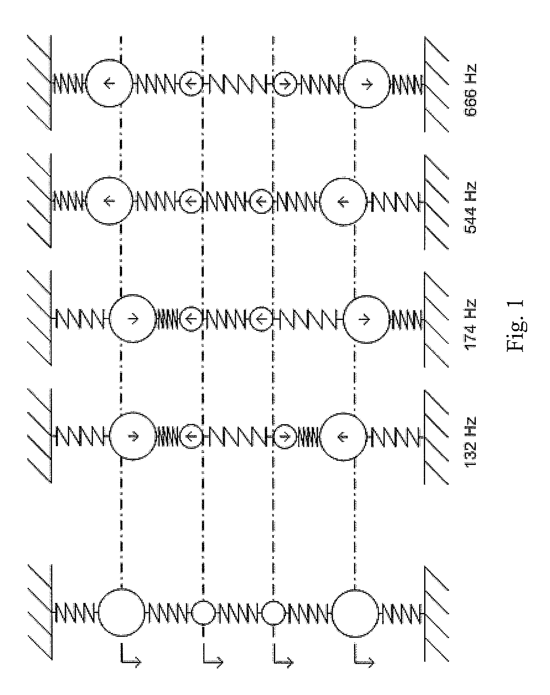
[0080]With reference to a cage according to FIG. 1, a simplified dynamic model of such a cage is shown. This shows typical vibration modes of the cage at different frequency values: in particular, in the example, the vibration modes are obtained for frequencies of 132, 174, 544 and 666 Hz, which depend on the dimensional and...


PUM

PropertyMeasurementUnit
cut-off frequenciesaaaaaaaaaa
frequenciesaaaaaaaaaa

Abstract

The present application relates to a vibration damping system for a rolling mill comprising a rolling cage and a bending adjustment system (3,3′) of the rollers comprising hydraulic actuators acting on the rollers and hydraulic circuits (18, 19) for feeding, and hydraulic damping means (25, 31, 32) of a force connected to the hydraulic circuits (18, 19) for actuating a damping effect by means of the hydraulic actuators. The hydraulic damping means comprises a pair of hydraulic pumps (25B, 25C) or a pair of hydraulic cylinders with a dual chamber, connected in an opposite direction to each other to the hydraulic circuits (18, 19).

Description

FIELD OF THE INVENTION[0001]The present invention relates to a vibration damping system for a rolling mill.PRIOR ART[0002]In the cold rolling of tapes, rolling cages are used comprising at least one pair of rolling cylinders called 1 and 1′ which are in direct contact with the tape during the rolling; see FIG. 10a in the technical note. One of the two rollers is vertically above the other one.[0003]This arrangement is limited in terms of the forces that can be applied for the elastic deformation of said cylinders. To solve this problem, cages are used comprising more rollers or cylinders, at least two of which are rollers, and two of which are support rollers or cylinders that oppose the elastic deformation of the rollers that are intended to be in direct contact with the material to be rolled.[0004]Other arrangements are known in the prior art, in which two cylinders are used for rolling, with two intermediate cylinders and two cylinders for support.[0005]In addition, arrangements ...

Claims


Application Information

Patent Timeline
Patent Type & Authority Patents(United States)
IPC IPC(8): B21B37/00F16F15/027B21B38/00
CPCB21B37/007B21B38/008F16F15/027B21B33/00B21B37/00F16F15/023
Inventor VIGNOLO, LUCIANODE LUCA, ANDREANOBILE, MATTEOAMATI, NICOLAPRISTERA', CARMINEROMEO, GIUSEPPETONOLI, ANDREA
Owner DANIELI & C OFF MEC SPA
Why Eureka
Try Eureka