Rail support assembly with improved shoulder

a technology of rail support and rails, applied in railway tracks, railway construction, ways, etc., can solve the problems of imposing a lot of pressure and torsional forces on rails, and the heavy weight of railroad cars

Active Publication Date: 2016-01-05
PANDROL LTD
View PDF24 Cites 0 Cited by
  • Summary
  • Abstract
  • Description
  • Claims
  • Application Information

AI Technical Summary

Problems solved by technology

This assembly has been found to be working reasonably well, however one problem with it is that typically railroad cars are extremely heavy and apply tremendous pressure and torsional forces on the rails, especially when rails curve.
As a result, sometimes whole sections of rails separate from the ties because the support assemblies are not able to resist these effects.

Method used


Image

  • Rail support assembly with improved shoulder
  • Rail support assembly with improved shoulder
  • Rail support assembly with improved shoulder

Examples


Embodiment Construction

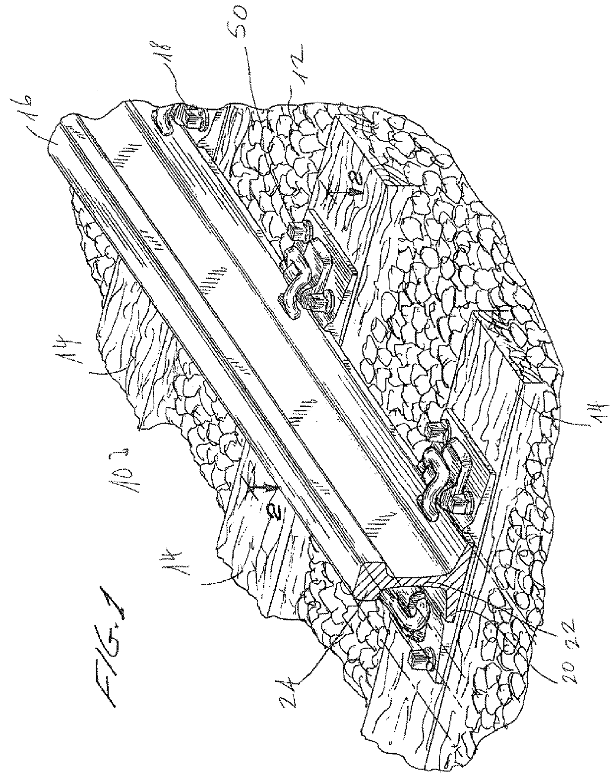
[0014]Referring first to FIG. 1, a railroad track 10 includes a track bed 12 with a plurality ties 14. Ties 14 are typically made of treated wood, or concrete. A rail 16 is supported on the ties 14 by a support assembly 18. The rail 16 includes a bottom flange 20, a vertical web 22 and a top 24. A second rail identical to rail 16 extends in parallel thereto but has been omitted for the sake of clarity.

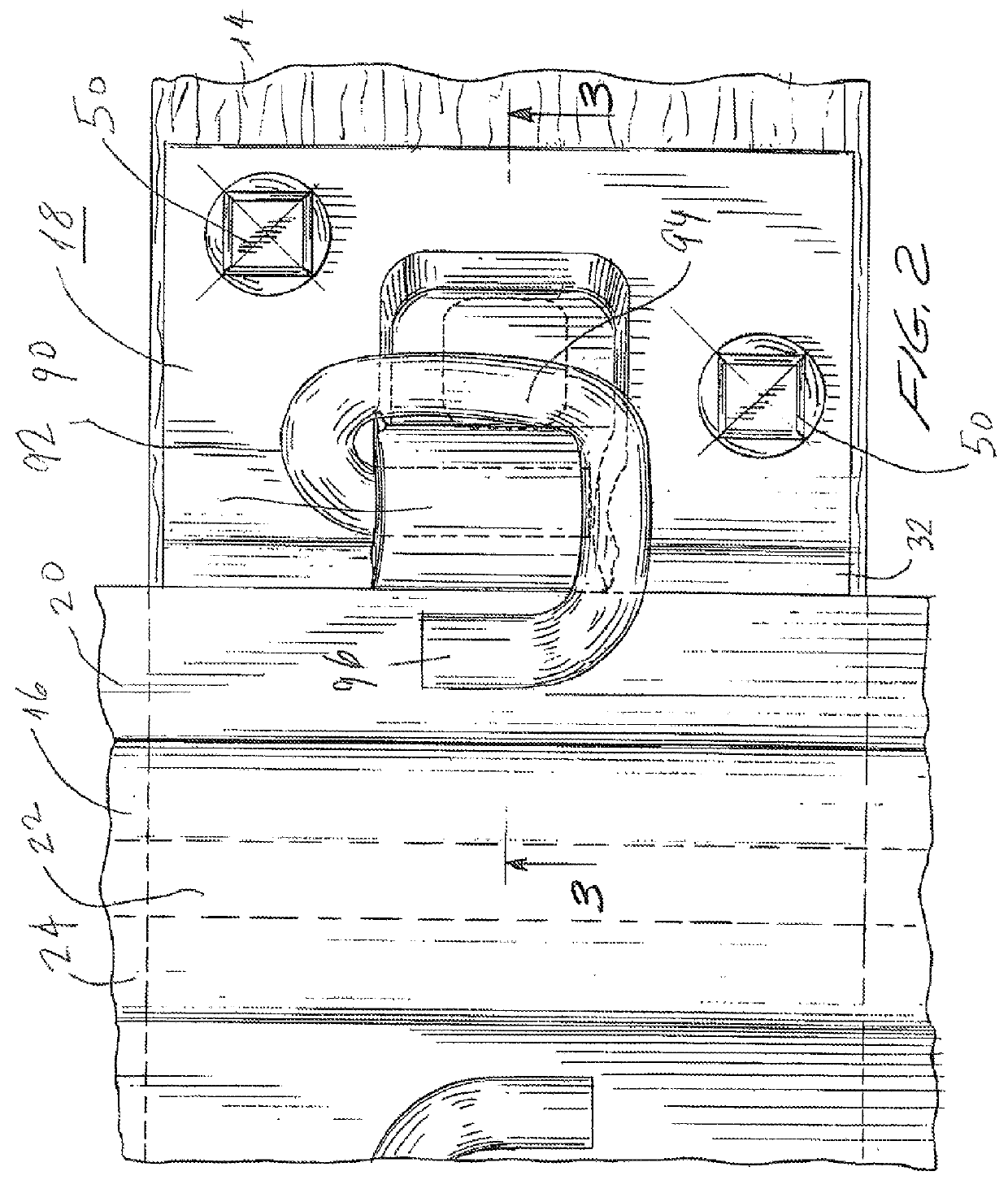
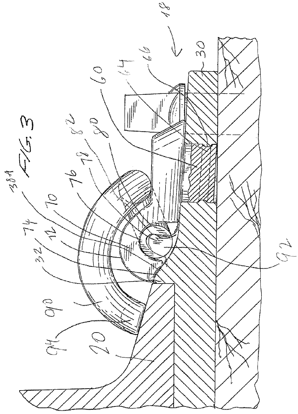
[0015]As shown more clearly in FIGS. 2-4, rail support assembly 18 includes a plate 30. Plate 30 is generally rectangular having a width substantially equal to the width of tie 14 and extending along the top surface of the tie 14. The plate 30 is formed with two transversal ridges 32A 32B. Each ridge includes a vertical wall 36A, 36B and a sloping wall 38A, 38B. The distance between the two vertical walls 36A, 36B is equal to the width W of the flange 20 of rail 16. Therefore the rail 16 can be seated solidly on top of the plate 18 with the flange 20 firmly seated between the ridges 32...


PUM


Abstract

A rail support assembly for mounting and supporting the rail of a railroad system, the assembly including a plate disposed under the rail and including a shoulder hole, a shoulder arranged and constructed to fit in said shoulder hole without rotation with respect to the plate, and a clip having an end received by said shoulder and arranged to bias the rail toward the plate.

Description

RELATED APPLICATIONS[0001]NoneFIELD OF INVENTION[0002]This invention pertains to a rail support assembly including a shoulder and a clip engaging the shoulder and arranged to hold a rail in place, the shoulder being shaped to prevent it from rotating with respect to a supporting plate.DESCRIPTION OF THE PRIOR ART[0003]Trains running on rails are the most efficient way of transporting all industrial, agricultural as well as consumer products. Typically rails are supported on ties by support assemblies including a bottom plate disposed on ties, a pair of shoulders disposed on top of the plate on either side of a rail and clips made of a steel bar formed into a predetermined shape and arranged to secure the rail. One end of each clip engages a respective shoulder and the rest of the clip rests on top of a rail flange and biases the flange (and therefore the rail) downward toward the plate.[0004]This assembly has been found to be working reasonably well, however one problem with it is t...

Claims


Application Information

Patent Timeline
Patent Type & Authority Patents(United States)
IPC IPC(8): E01B13/02E01B9/44
CPCE01B9/44
Inventor COATS, FRANK, HOWARD
Owner PANDROL LTD
Why Eureka
Try Eureka