System, method and calibration plate employing embedded 2D data codes as self-positioning fiducials

Active Publication Date: 2016-01-05
COGNEX CORP
View PDF8 Cites 57 Cited by
  • Summary
  • Abstract
  • Description
  • Claims
  • Application Information

AI Technical Summary

Benefits of technology

[0016]In accordance with the illustrative embodiment, a procedure for calibrating one or more vision system camera(s) commences by acquiring an image of at least a portion of a calibration plate when the calibration plate is stationary in the field of view. The image(s) are acquired by the camera(s) either where no relative motion of the plate with respect to the camera(s) occurs (i.e. standard non-hand-eye calibration) or at (at least) two times, one before motion and one after motion, when relative motion exists between the calibration plate and the camera(s) (i.e. hand-eye calibration). The calibration plate includes a plurality of 2D codes arranged on a checkerboard pattern. In embodiments where a plurality of cameras (at least a first camera and a second camera) are used to image the scene, the system decodes at least one visible 2D code (and potentially more than one 2D codes, or all 2D codes) within the field of view of the first camera. The system also decodes at least one 2D code (and potentially more than one 2D codes, or all 2D codes) within the field of view of the second camera. The field of view position for each camera with respect to the calibration plate is determined by finding/measuring corner positions, which serve as calibration features, on the remaining tiles surrounding 2D codes, while the codes serve to identify locations of tiles and associated corners in the global calibration plate coordinate system.
[0017]

Problems solved by technology

Generally, there are at least three disadvantages to a conventional calibration plate, such as a calibration plate employing a traditional checkerboard pattern with repeated (e.g. tessellated) identical-appearance calibration fiducials, each serving as a local origin in the coordinate system of the calibration plate.
However, the circular dots are known to have lower calibration accuracy when there are perspective and radial distortions.
Additionally, there are at least two disadvantages associated with the square cells.
First, the cells must be large

Method used


Image

  • System, method and calibration plate employing embedded 2D data codes as self-positioning fiducials
  • System, method and calibration plate employing embedded 2D data codes as self-positioning fiducials
  • System, method and calibration plate employing embedded 2D data codes as self-positioning fiducials

Examples


Embodiment Construction

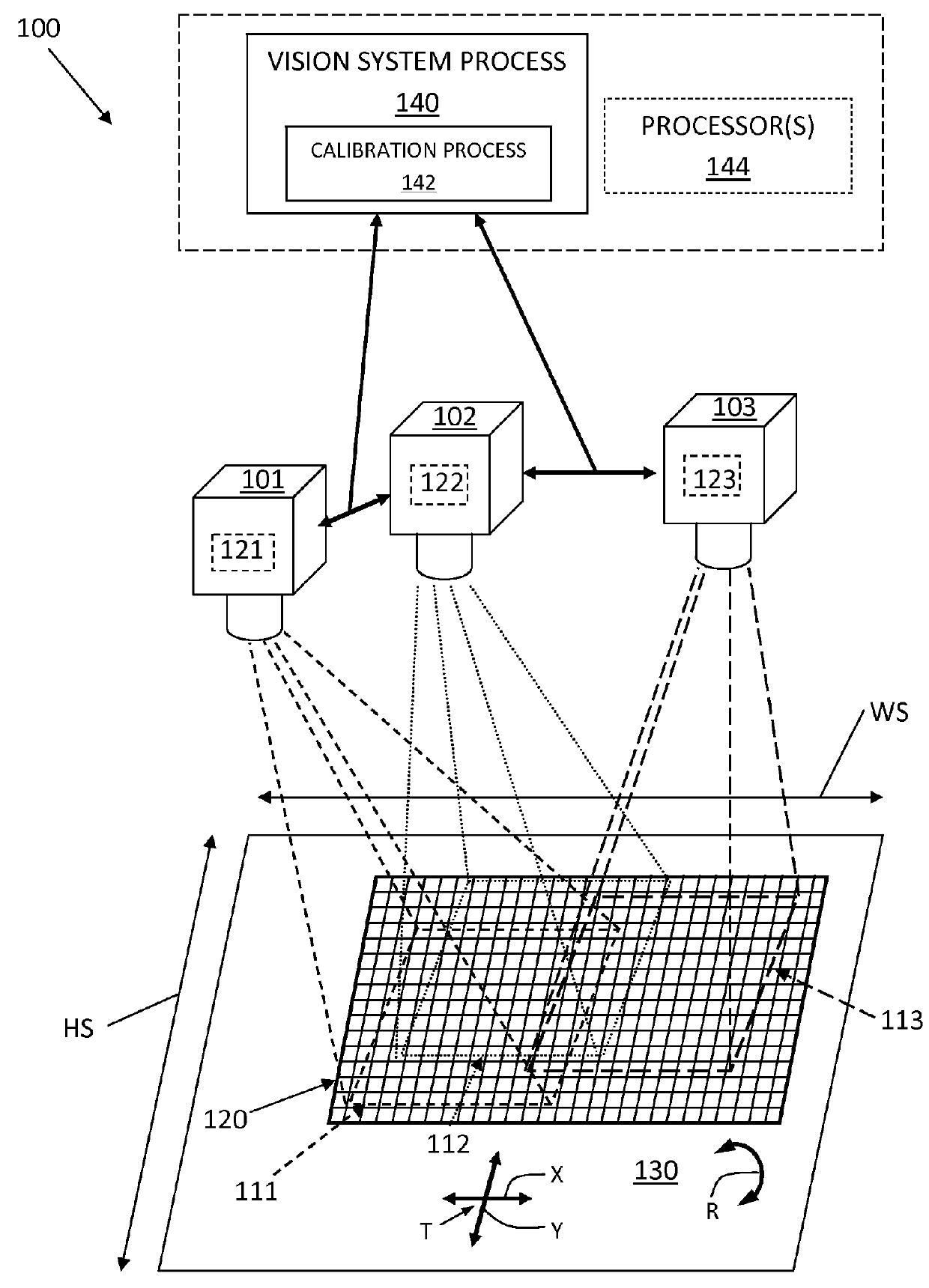
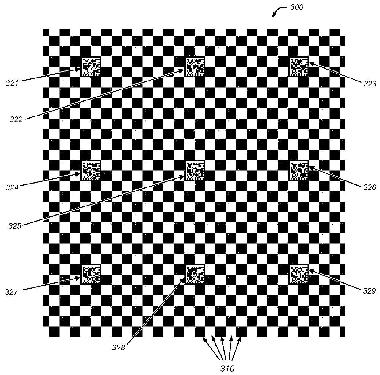
[0024]In overview, a system for calibrating one or more cameras in a machine vision system (termed briefly “vision system”) includes a calibration plate having a plurality of two-dimensional (2D) codes arranged thereon for automatic (i.e. non-manual) calibration of the camera(s) in the vision system. In an illustrative embodiment, the calibration (either hand-eye calibration or standard non-hand-eye calibration) is performed to align flat work pieces to a piece of process equipment, such as in screen printing cover lenses of cell phones, computing tablets (such as Apple iPads®) and flat-panel displays, for example. The 2D codes (in this example consisting of DataMatrix-type codes) are arranged at a moderate density such that a good balance of image resolution requirements, feature coverage requirements, and requirement that at least one code always remain visible (capable of being fully imaged / decodable) in the camera field of view, is achieved. In an illustrative embodiment, each 2...


PUM


Abstract

This invention provides a system and method for automatic (non-manual) calibration of one or more cameras employs a tessellating calibration plate having a checkerboard tile pattern and a plurality of 2D codes embedded within the checkerboard pattern. Each 2D code encodes the (X,Y) coordinates that identify tile calibration feature locations in the pattern, and the remaining, surrounding tiles allow measurement of the corner positions as calibration features. One or more vision system camera(s) can be calibrated to a single coordinate system automatically. During calibration, an image of at least a portion of a calibration plate is acquired, the encoded data is decoded for at least one 2D code within the field of view of each camera and then the position of the field of view is determined on the calibration plate for each camera using the 2D code data and the checkerboard tile pattern.

Description

FIELD OF THE INVENTION[0001]The present invention relates to systems, methods and calibration plates used in machine vision system applications.BACKGROUND OF THE INVENTION[0002]In machine vision systems (also termed herein “vision systems”), one or more cameras are used to perform vision system process on an object or surface within an imaged scene. These processes can include inspection, decoding of symbology, alignment and a variety of other automated tasks. More particularly, a vision system can be used to inspect a flat work piece passing through an imaged scene. The scene is typically imaged by one or more vision system cameras that can include internal or external vision system processors that operate associated vision system processes to generate results. It is generally desirable to calibrate one or more cameras to enable it / them to perform the vision task(s) with sufficient accuracy and reliability. A calibration plate can be employed to calibrate the cameras.[0003]A calibr...

Claims


Application Information

Patent Timeline
IPC IPC(8): H04N17/00G06T7/00H04N9/093
CPCG06T7/0018G06T2207/10016G06T2207/30208G06T7/80
Inventor LIU, GANG
Owner COGNEX CORP
Why Eureka
Try Eureka