Interferometer using integrated imaging array and high-density polarizer array

a high-density polarizer array and interferometer technology, applied in the field of interferometers, can solve problems such as adversely affecting high-precision interferometry measurements

Inactive Publication Date: 2005-02-01
MITUTOYO CORP
View PDF6 Cites 20 Cited by
  • Summary
  • Abstract
  • Description
  • Claims
  • Application Information

AI Technical Summary

Benefits of technology

These and other features and advantages of this invention are described in, or are apparent from, the following detailed description of various exemplary embodiments of the systems and methods according to this invention.

Problems solved by technology

However, the multiple phase-shifting image generating structure disclosed in the 330 patent introduces new sources of non-common-mode errors that can adversely affect high-precision interferometry measurements.

Method used


Image

  • Interferometer using integrated imaging array and high-density polarizer array
  • Interferometer using integrated imaging array and high-density polarizer array
  • Interferometer using integrated imaging array and high-density polarizer array

Examples


Embodiment Construction

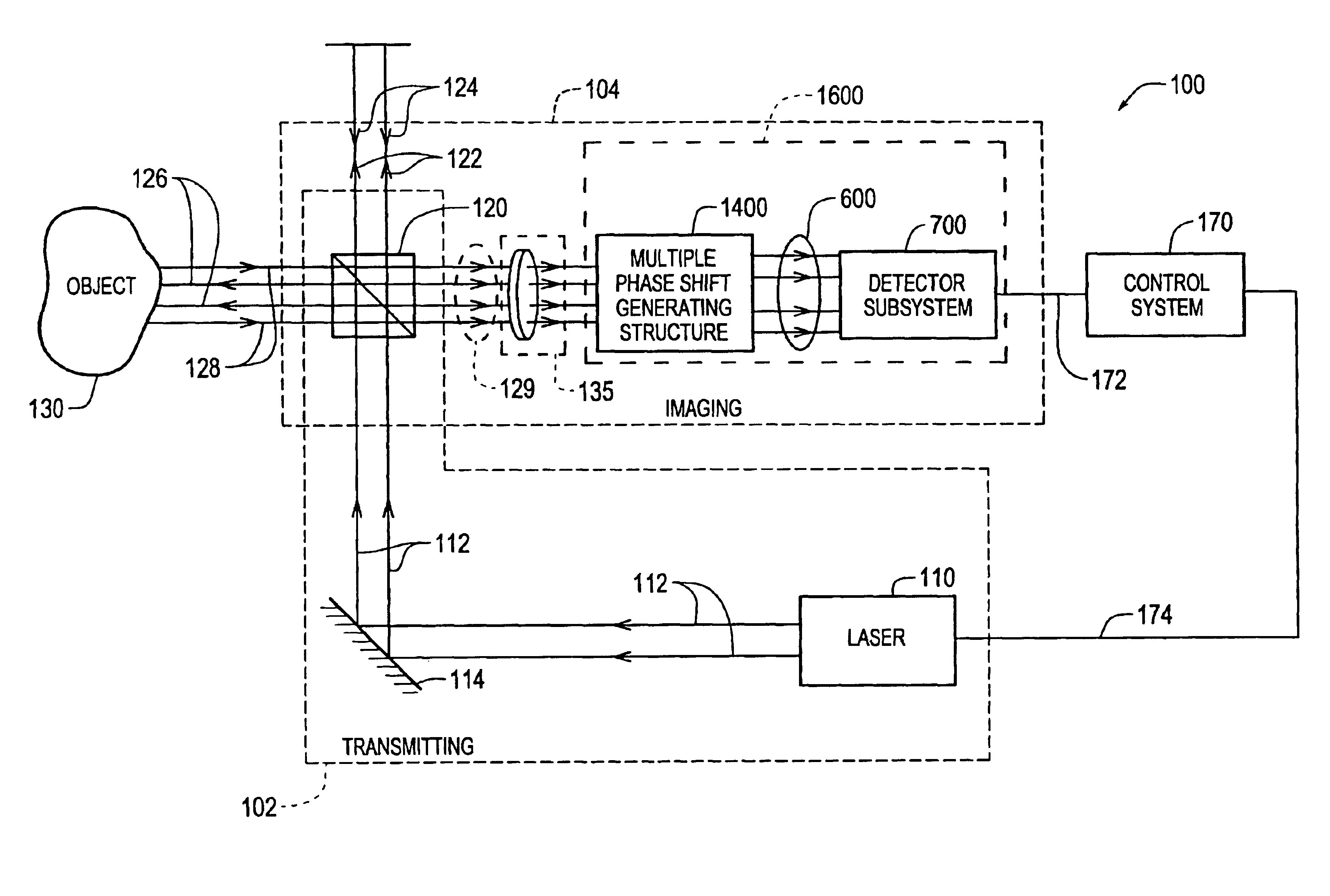
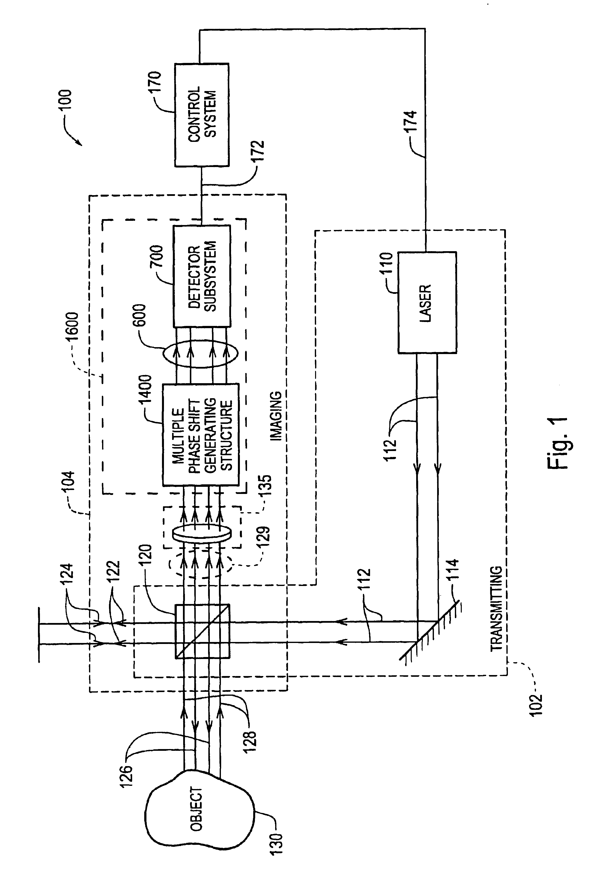
FIG. 1 shows one exemplary embodiment of an interferometer 100 with which the various exemplary embodiments of the phase-shift imaging element and other optical elements according to this invention are usable. As shown in FIG. 1, the interferometer 100 generally includes a transmitting portion 102 and an imaging portion 104. The transmitting portion 102 includes a laser source 110 that transmits a coherent light wavefront 112. In various exemplary embodiments, the laser source 110 may include two lasers, wavelength modulation, or any other known or later-developed device, structure or apparatus that provides at least two wavelengths of light at different times, for the coherent light wavefront 112. As used herein, the term “light” encompasses not only visible light, but any part of the electromagnetic spectrum that is otherwise usable according to the principles of this invention. When at least two wavelengths of light are provided, the interferometer 100 may provide certain types o...


PUM


Abstract

An integrated imaging element for an interferometer generates at least one image that includes multiple interference portions with different relative phase shifts interleaved in a pattern having a high spatial frequency in the image. The interleaved pattern is at least partially determined by the pattern of a high density polarizing array used in the integrated imaging element. In various embodiments, the multiple interference portions are interleaved in a checkerboard pattern across the entire surface of a detector device. As a result, various non-common mode errors present in various interferometers that generate separate non-interleaved images for each relative phase are reduced or eliminated because multiple phase-shifted interference image information for a small region of an object is provided within a small region on the detector device.

Description

BACKGROUND OF THE INVENTION1. Field of InventionThis invention is directed to an interferometer that includes improved polarizing and phase shifting structures.2. Description of Related ArtU.S. Pat. No. 6,304,330, which is incorporated herein by reference for all of its relevant teachings, discloses a novel multiple phase-shifting image generating structure that combines a wavefront-spreading element, a phase-shifting interference element and a sensing element. By combining the wavefront-spreading element, the phase-shifting interference element, and the sensing element, the multiple phase-shifting image generating structure shown in the 330 patent is able to convert many sources of potential error in interferometry measurements into common-mode errors. That is, these errors, in view of the multiple phase-shifting image generating structure disclosed in the 330 patent, equally affect all of the interferometry measurements. As a result, the magnitude and direction of these common-mod...

Claims


Application Information

Patent Timeline
Patent Type & Authority Patents(United States)
IPC IPC(8): G01B9/02
CPCG01B9/02056G01B9/02081G01B2290/70
Inventor TOBIASON, JOSEPH D.ATHERTON, KIM W.
Owner MITUTOYO CORP
Why Eureka
Try Eureka