Optical coherence tomography with 3d coherence scanning

a coherence scanning and optical coherence technology, applied in the field of optical coherence scanning with 3d coherence scanning, can solve the problems of reducing the sensitivity of eye movement, no 3d image appears to be produced by the apparatus, and no 3d image is described in the paper

Inactive Publication Date: 2009-01-06
APPLIED SCI INNOVATIONS +1
View PDF101 Cites 156 Cited by
  • Summary
  • Abstract
  • Description
  • Claims
  • Application Information

AI Technical Summary

Problems solved by technology

Despite the wealth of literature in this area, none of these papers describes 3D coherence scanning.
However, no 3D image appears to be produced by the apparatus.
This design decreases sensitivity to eye movement.
A drawback of the apparatus is the potentially low-frequency detection typical of CCD.
The extent of resolution improvement was limited due to noise, as described in M. D. Kulkarni, C. W. Thomas, and J. A. Izatt, Image enhancement in optical coherence tomography using deconvolution, Electron. Lett., vol.
The device is inherently large and is not fiberoptic.
The drawbacks include large probe size, potentially slower operating with the CCD-type detector, and likely cross-talk between fibers producing artifacts in the output image.
The drawback of the method is the possible effect of spectral variation of scattering by the object.
The need for mechanical motion of elements at the tip of the fiber probe adds complexity and cost to the device, and may compromise its range of applications and reliability.
These instruments have several limitations, including:Bulky probe tipSlow operationLimited depth of fieldLimited speed of image acquisitionRigid probe limiting the scope of applicationsLarge (mm) probe tip diameter, making the use of OCT problematic for many in-vivo imaging tasksHigh cost of the OCT systemLow productivity and high cost of procedure

Method used


Image

  • Optical coherence tomography with 3d coherence scanning
  • Optical coherence tomography with 3d coherence scanning
  • Optical coherence tomography with 3d coherence scanning

Examples


Embodiment Construction

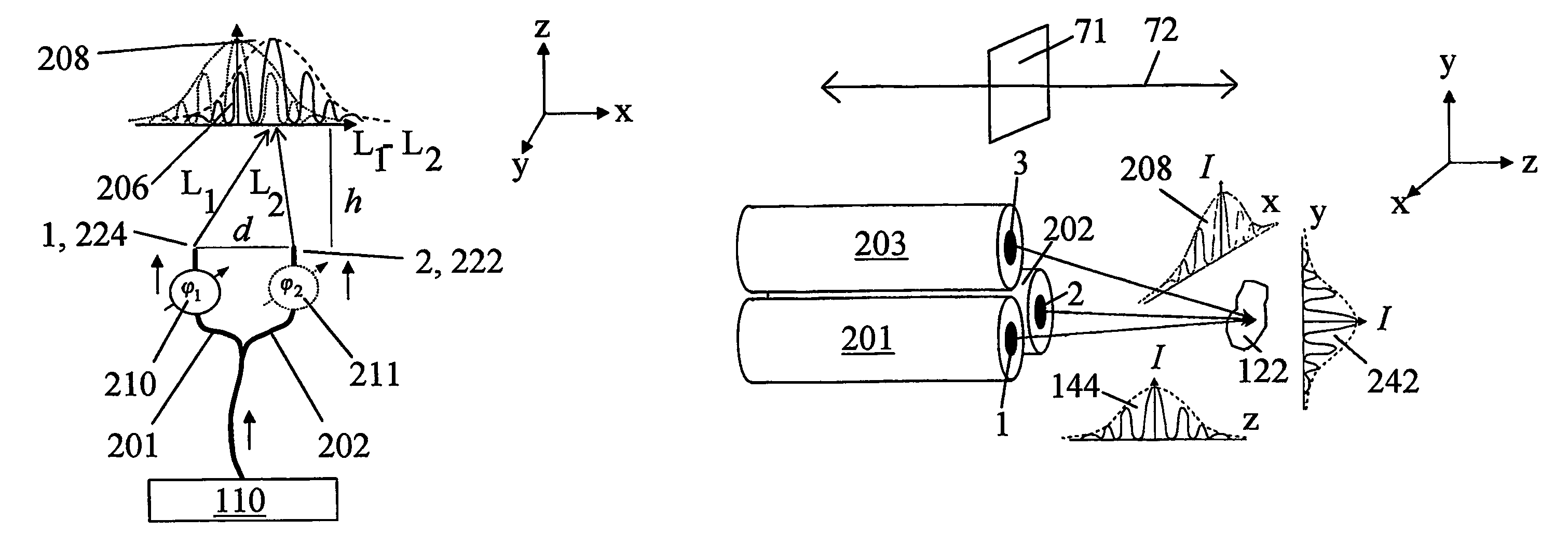
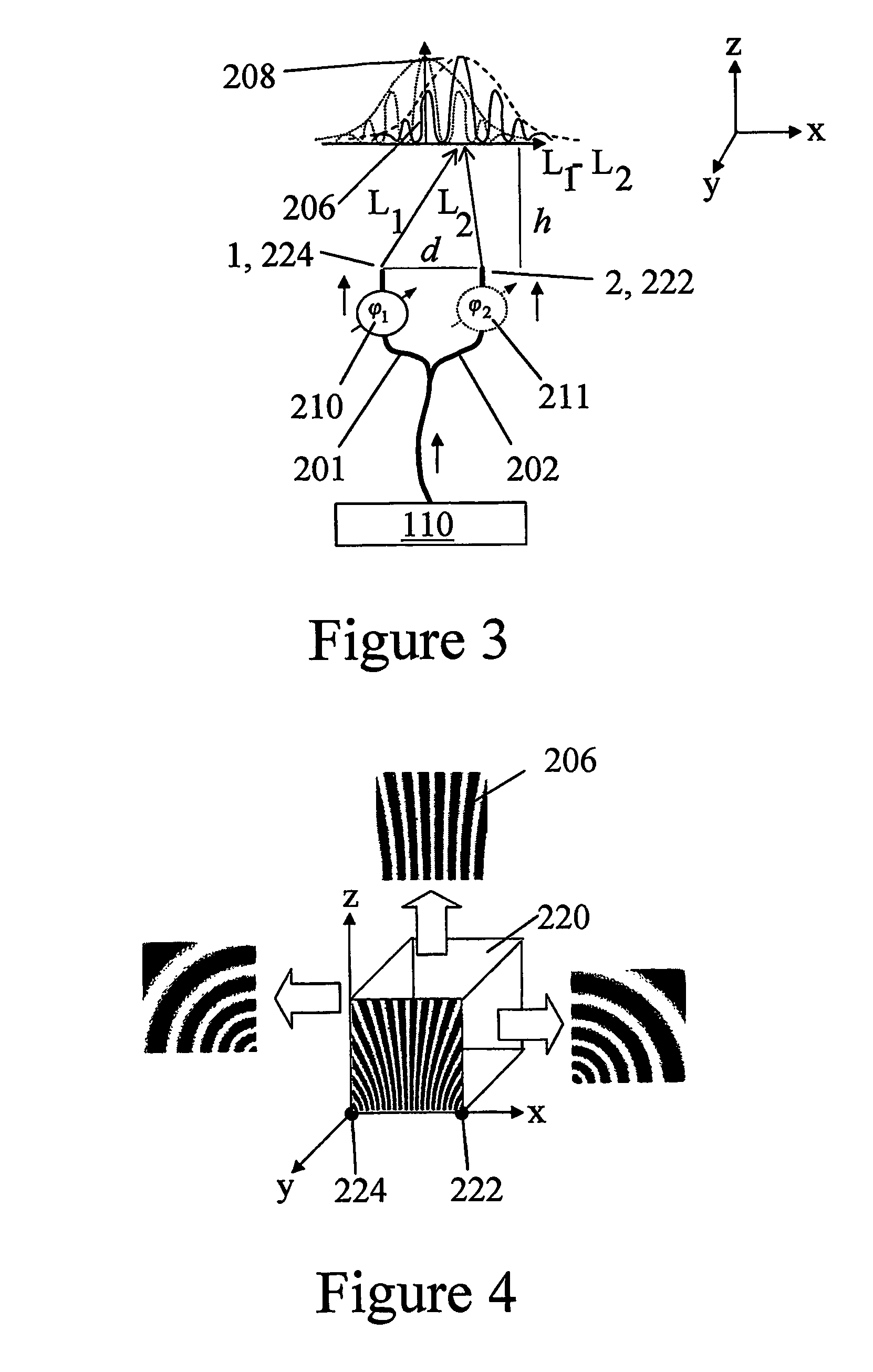
[0131]Disclosed herein is a new fiberoptic OCT system with coherence 3D scanning of an object 122 to be scanned. The concept is based on using multiple fibers for illumination and / or collection of light from a sample. Referring to FIG. 3, we begins by considering consider a first fiber 201 and a second fiber 202 of equal lengths connected to a common low-coherence light source 110, each emitting a diverging beam, so that there is an area where the beams overlap. In the area of overlap, interference of the beams will take place. A resulting x-fringe pattern 206 will vary in the x,y plane, normal to the regular OCT coherence scan in z-direction.

[0132]FIG. 4 illustrates the 3D x-fringe pattern produced by light from these two fibers, which can be made by considering cross-sections of the pattern by sides of a cube 220, with the light sources (fiber tips 1 and 2) at two corners 222 and 224 along the x axis. The scale of the fringes is arbitrary and is chosen for illustration purposes on...


PUM

PropertyMeasurementUnit
diameteraaaaaaaaaa
volumeaaaaaaaaaa
areaaaaaaaaaaa

Abstract

Optical coherence tomography with 3D coherence scanning is disclosed, using at least three fibers (201, 202, 203) for object illumination and collection of backscattered light. Fiber tips (1, 2, 3) are located in a fiber tip plane (71) normal to the optical axis (72). Light beams emerging from the fibers overlap at an object (122) plane, a subset of intersections of the beams with the plane defining field of view (266) of the optical coherence tomography apparatus. Interference of light emitted and collected by the fibers creates a 3D fringe pattern. The 3D fringe pattern is scanned dynamically over the object by phase shift delays (102, 104) controlled remotely, near ends of the fibers opposite the tips of the fibers, and combined with light modulation. The dynamic fringe pattern is backscattered by the object, transmitted to a light processing system (108) such as a photo detector, and produces an AC signal on the output of the light processing system (108). Phase demodulation of the AC signal at selected frequencies and signal processing produce a measurement of a 3D profile of the object.

Description

BACKGROUND OF THE INVENTION[0001]This invention relates to optical coherence tomography (OCT), specifically to fiber OCT with coherence scanning in three dimensions.[0002]OCT known in the prior art typically involves one-dimensional coherence gating (scanning) in what will be illustrated herein as the “z” dimension, combined with mechanical scanning in the two remaining “x” and “y” dimensions, to produce a 3D image of a scattering object The invention to be disclosed herein provides an OCT apparatus with coherence scanning in all three dimensions and a method for implementation of such a scanning.[0003]The literature contains numerous papers regarding various types of OCT and related scanning. For example:[0004]S. A. Boppart, W. Drexler, U. Morgner, F. Kartner, J. Fujimoto, Ultrahigh Resolution and Spectroscopic OCT Imaging of Cellular Morphology and Function, Proc. Inter-Institute Workshop on In Vivo Optical Imaging at the National Institutes Health. Ed. A. H. Gandjbakhche. Septemb...

Claims


Application Information

Patent Timeline
Patent Type & Authority Patents(United States)
IPC IPC(8): G01B9/02A61BG01N21/47
CPCA61B5/0066A61B5/411G01N21/45G01N21/4795G01B9/0201G01B9/02012G01B9/02007G01B9/02027G01B9/02002G01B9/02091G01B9/02034A61B5/0068A61B5/0075A61B5/0084A61B5/7203A61B5/7257G01N2021/1787G01N2021/458G01N2021/4709G01N2021/4742G01N2201/0691G01N2201/08G01B2290/65
Inventor GUTIN, MIKHAIL
Owner APPLIED SCI INNOVATIONS
Why Eureka
Try Eureka