Scanning system for differential phase contrast imaging

a scanning system and imaging technology, applied in the field of xray imaging, can solve the problems of reducing the exposure of patients to x-rays, reducing the contrast to noise ratio, and reducing the total harmful effect of x-ray exposure on patients, and reducing the dose of x-rays

Active Publication Date: 2017-09-05
KONINKLIJKE PHILIPS ELECTRONICS NV
View PDF21 Cites 143 Cited by
  • Summary
  • Abstract
  • Description
  • Claims
  • Application Information

AI Technical Summary

Benefits of technology

[0006]A further problem may arise from incoherently scattered X-ray radiation, which may be scattered by the object. The additionally scattered photons may create an unwished signal offset in the absorption image and may decrease the contrast to noise ratio not only in absorption image but also in the differential phase-contrast image.
[0061]This may have the advantage that the X-ray dose a patient is exposed may be decreased. If a large detector is used, a local illuminating X-ray intensity is directly coupled to the tube load, which means that the dose which may be optimally adapted to a first part of the image area might not be optimally adapted to another area of the image area, which, for example, may be caused by different object thicknesses at the two areas. The applied X-ray intensity is adapted to the local object properties during the overall scan, in order to optimize the deposited dose for a more homogeneous contrast to noise ratio in the image.

Problems solved by technology

In particular, if the distance orthogonal to the grating orientation is considered, the visibility may drop quickly due to the misalignment between the trenches of the gratings and the X-rays.
Otherwise, intended rectangular profiles for X-ray absorption or X-ray phase-shift become trapezoidal distant from the optical center, which may result in a strong decrease in the visibility of interference pattern and therefore in a degradation of the contrast to noise ratio.
A further problem may arise from incoherently scattered X-ray radiation, which may be scattered by the object.

Method used


Image

  • Scanning system for differential phase contrast imaging
  • Scanning system for differential phase contrast imaging
  • Scanning system for differential phase contrast imaging

Examples


Embodiment Construction

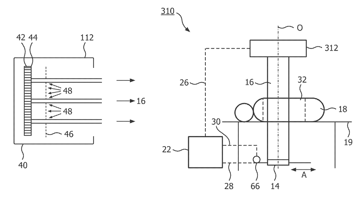
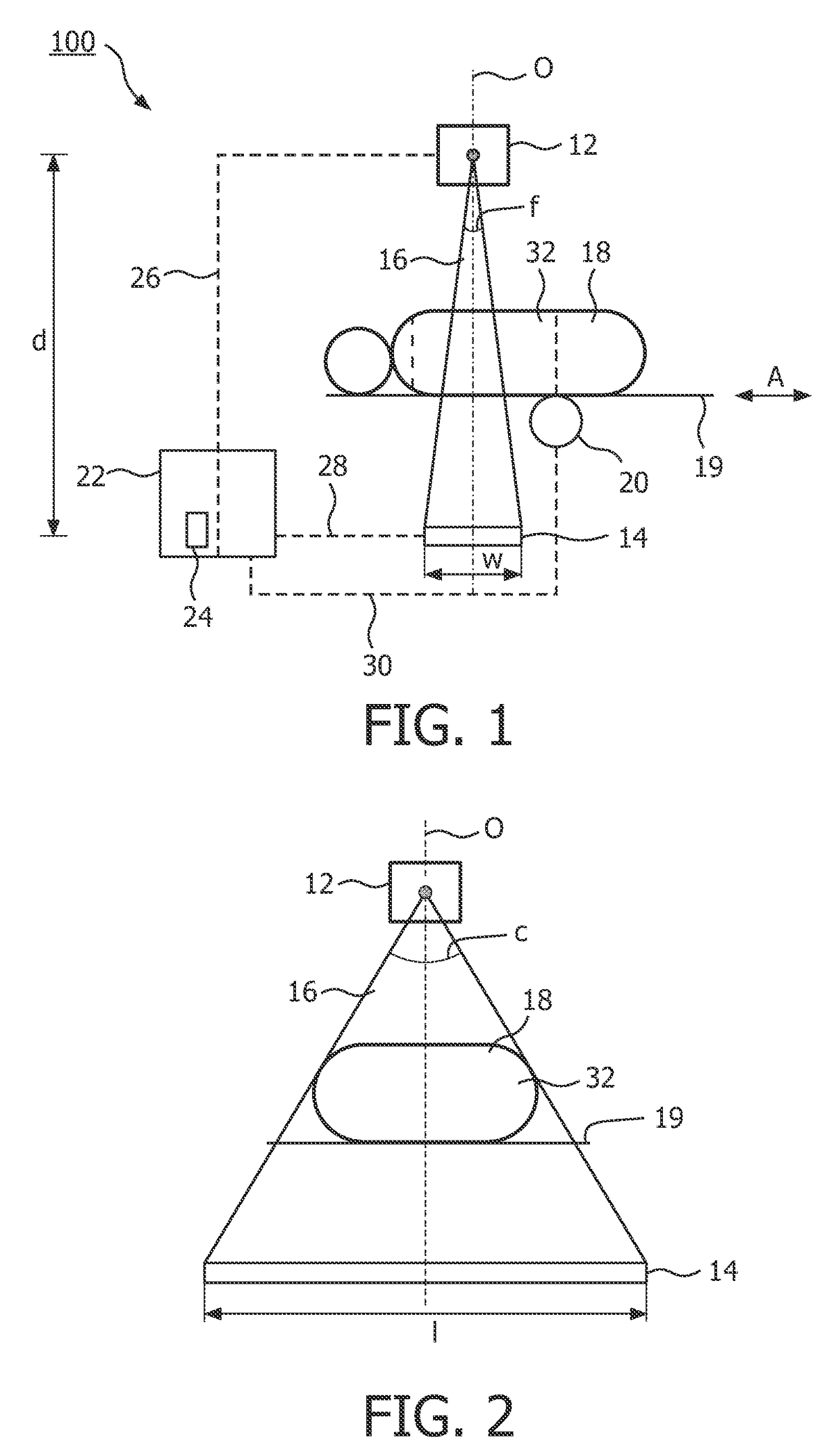
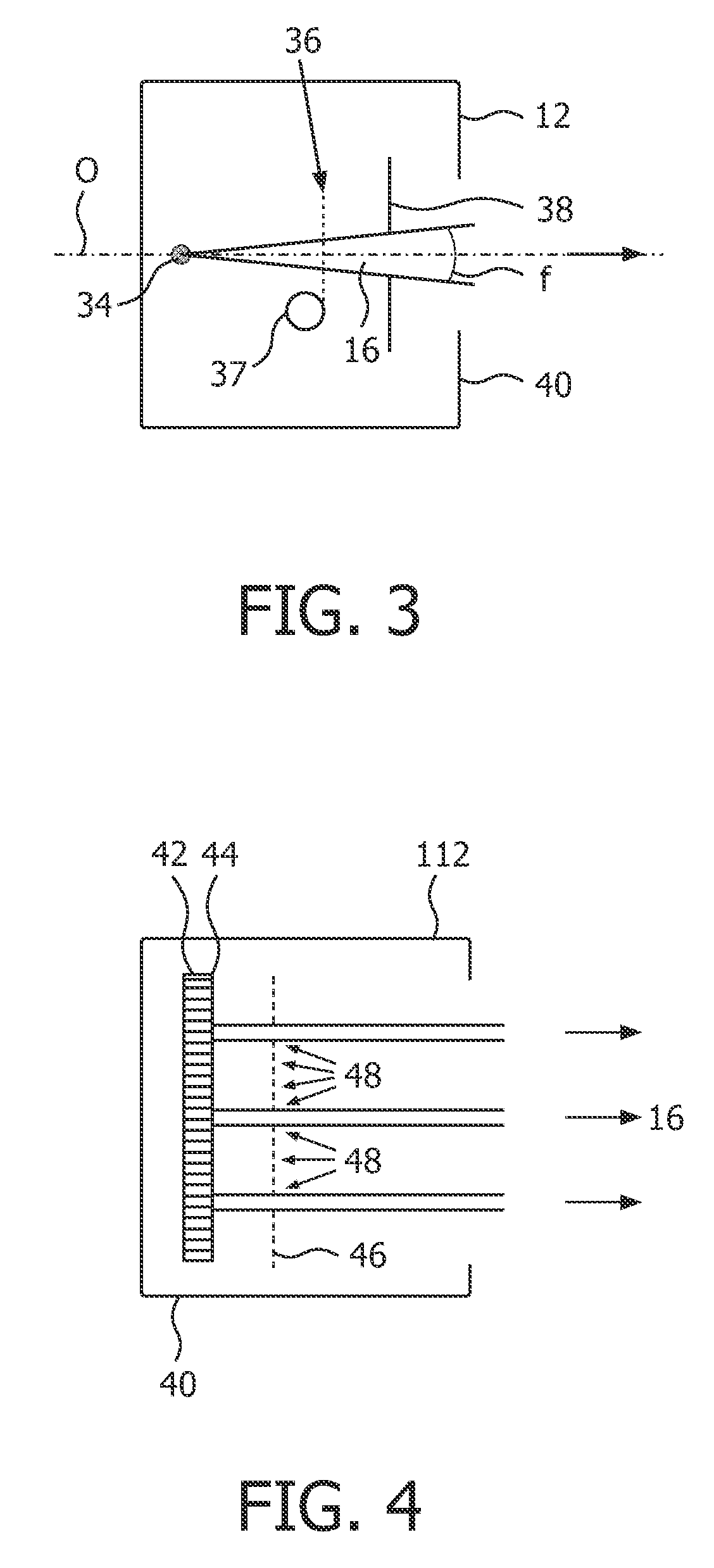
[0093]FIG. 1 shows schematically an X-ray device 10 with an X-ray emitter arrangement 12 and an X-ray detector arrangement 14. The X-ray emitter arrangement 12 is adapted to emit a fan-shaped and at least partial coherent X-ray beam 16. The X-ray beam 16 is transmitted through an object 18 for example a human being, on a table 19.

[0094]In the embodiment shown in FIG. 1, the X-ray emitter arrangement 12 and the X-ray detector arrangement 14 are stationary with respect to the environment of the X-ray device 10 and the object 18 may be moved in an axial direction A orthogonal to the optical axis O of the X-ray device 10. For moving the table 19 in the axial direction A, the X-ray device 10 comprises an actuator 20, for example step motor 20, that is adapted to move the table 19 with the object 18 in small steps in the axial direction A.

[0095]The X-ray device 10 further has a controller 22 with a processor 24. The controller 22 is connected to the X-ray emitter arrangement 12 over a sig...


PUM


Abstract

The invention relates to the field of X-ray differential phase contrast imaging. For scanning large objects and for an improved contrast to noise ratio, an X-ray device (10) for imaging an object (18) is provided. The X-ray device (10) comprises an X-ray emitter arrangement (12) and an X-ray detector arrangement (14), wherein the X-ray emitter arrangement (14) is adapted to emit an X-ray beam (16) through the object (18) onto the X-ray detector arrangement (14). The X-ray beam (16) is at least partial spatial coherent and fan-shaped. The X-ray detector arrangement (14) comprises a phase grating (50) and an absorber grating (52). The X-ray detector arrangement (14) comprises an area detector (54) for detecting X-rays, wherein the X-ray device is adapted to generate image data from the detected X-rays and to extract phase information from the X-ray image data, the phase information relating to a phase shift of X-rays caused by the object (18). The object (18) has a region of interest (32) which is larger than a detection area of the X-ray detector (18) and the X-ray device (10) is adapted to generate image data of the region of interest (32) by moving the object (18) and the X-ray detector arrangement (14) relative to each other.

Description

FIELD OF THE INVENTION[0001]The invention relates to the field of X-ray imaging. In particular, the invention relates to an X-ray device for imaging an object, a method for controlling an X-ray device, a computer-readable medium and a program element.BACKGROUND OF THE INVENTION[0002]X-ray differential phase-contrast imaging (DPCI) visualizes the phase information of coherent X-rays passing a scanned object. In addition to classical X-ray transmission imaging, DPCI may determine not only the absorption properties of the object along a projection line, but also the phase-shift of the transmitted X-rays, and thus may provide valuable additional information. After the object, a phase-shifting grating (also known as phase grating) is placed, working as a beam splitter. The resulting interference pattern contains the required information about the beam phase-shift in the relative position of its minima and maxima, typically in the order of several micrometers. Since a common X-ray detecto...

Claims


Application Information

Patent Timeline
Patent Type & Authority Patents(United States)
IPC IPC(8): A61B6/00A61B6/03
CPCA61B6/00A61B6/4291A61B6/484A61B6/488A61B6/032A61B6/5241
Inventor ENGEL, KLAUS JUERGENGELLER, DIETERVOGTMEIER, GEREONKOEHLER, THOMAS
Owner KONINKLIJKE PHILIPS ELECTRONICS NV
Why Eureka
Try Eureka