Passive harmonic switch mixer

a mixer and harmonic switch technology, applied in the field of mixers, can solve the problems of severe flicker noise at the low frequency, complex circuit design, and reduce the signal-to-noise ratio seen at the output bb por

Active Publication Date: 2006-02-14
REALTEK SEMICON CORP
View PDF10 Cites 148 Cited by
  • Summary
  • Abstract
  • Description
  • Claims
  • Application Information

AI Technical Summary

Problems solved by technology

The main advantage of the active mixer is the addition of signal gain to the output signal; however, it has the disadvantage that the low frequency flicker noise problem is severe.
In this manner, the circuit design is complicated by the difficult to implement impedance-matching issues.
Additionally, flicker noise, which is caused by the input noise of a transistor logic component and is inversely proportional with frequency, reduces the signal to noise ratio seen at the output BB port.
The direct conversion receiver, as well as a direct conversion transmitter, suffer from the same leakage noise, DC offset, and flicker noise problems.
The problems are due to the strong RF signal being centered at the same frequency as the local oscillator signal and a portion of this signal being leaked back to the local oscillator and injected into the mixer where it is mixed with the local oscillator signal.
This injection occurs due to non-ideal isolation between the local oscillator and the amplifier.
Even if careful shielding techniques are used, there is still a finite amount of radiation and or conduction of the RF output signal back to the local oscillator.
In addition, the direct conversion transmitter also suffers from pulling noise resulting from the voltage variation of VDD and Ground during ON and OFF switching of the power amplifier.
Pulling noise may cause serve frequency shifting of the power amplifier in the direct conversion transmitter.

Method used


Image

  • Passive harmonic switch mixer
  • Passive harmonic switch mixer
  • Passive harmonic switch mixer

Examples


Embodiment Construction

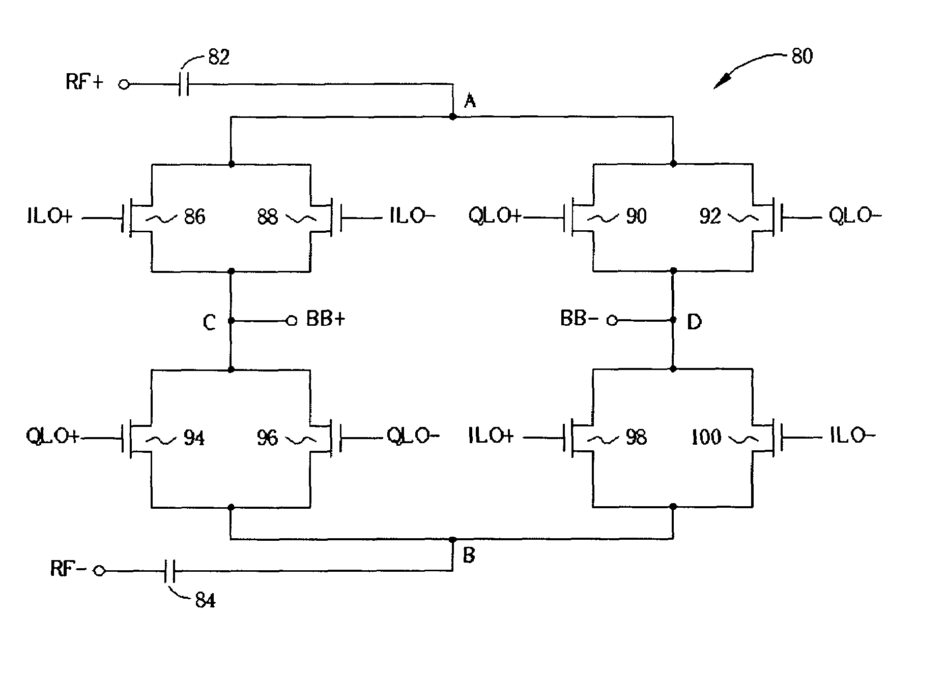
[0025]FIG. 5 is a schematic diagram of a passive harmonic switch mixer 80 according to the present invention. The passive harmonic switch mixer 80 includes a first input port A and a second input port B for receiving a differential RF signal pair having a positive signal RF+ and a negative signal RF− respectively. A first output port C and a second output port D are for outputting a differential baseband signal pair having a positive signal BB+ and a negative signal BB− respectively. A positive side capacitor 82 is connected to the node A and a negative capacitor 84 is connected to node B for DC isolation. There are four switch pairs for mixing the differential RF signal pair RF+ and RF− with two pairs of differential local oscillator signals, which includes an in-phase differential local oscillator signal pair ILO+ and ILO− and a quadrature-phase differential local oscillator signal pair QLO+ and QLO−, to generate a positive signal BB+ and a negative signal BB−. The first switch pa...


PUM


Abstract

A passive harmonic switch mixer is shown that is immune to self mixing of the local oscillator greatly reducing leakage noise, pulling noise, and flicker noise when used in a direct conversion receiver or direct conversion transmitter circuit. The passive harmonic switch mixermixes an input signal received on an input port with an in-phase oscillator signal and a quadrature-phase oscillator signal and outputs an output signal on an output port. Because the quadrature-phase oscillator signal is the in-phase oscillator signal phase shifted by 90 °, the passive harmonic switch mixer operates with a local oscillator running at half the frequency of the carrier frequency of an RF signal. Additionally, because the passive harmonic switch mixer has no active components, the DC current passing through each switch device is reduced and the associated flicker noise of the mixer is also greatly reduced.

Description

BACKGROUND OF INVENTION[0001]1. Field of the Invention[0002]The invention relates to a mixer, and more particularly, to a passive harmonic switch mixer for use in a direct conversion receiver or a direct conversion transmitter.[0003]2. Description of the Prior Art[0004]FIG. 1 shows a conventional passive mixer 10. The mixer, which is for mixing a differential RF signal pair RF+ and RF− with a differential local oscillator signal to output a differential baseband signal pair BB+ and BB−, is a very important component in communication systems. There are two types of mixers: the active mixer and the passive mixer. The conventional passive mixer 10, shown in FIG. 1, includes a first input port A and a second input port B for receiving a differential RF signal pair RF+ and RF− respectively and a first output port C and a second output port D for outputting a differential baseband signal pair BB+ and BB− respectively. A positive side capacitor 12 is connected to the node A and a negative ...

Claims


Application Information

Patent Timeline
Patent Type & Authority Patents(United States)
IPC IPC(8): H04B1/26H04B1/28H03D7/16
CPCH03D7/165
Inventor SU, TUNG-MING
Owner REALTEK SEMICON CORP
Why Eureka
Try Eureka