Solar concentrator reflection mirror shape detection device and method based on optical imaging

A technology of solar concentrator and mirror surface, which is applied in the direction of using optical devices, optical instrument testing, measuring devices, etc., can solve the problem that the mirror surface is difficult to achieve, cannot obtain the normal characteristics of the actual condenser mirror surface, and cannot be effectively evaluated. Reflecting mirror surface light reflection performance and other issues, to achieve the effect of convenient installation, wide application range, fast and convenient detection process

Active Publication Date: 2015-11-18
HUNAN UNIV OF SCI & TECH
View PDF7 Cites 17 Cited by
  • Summary
  • Abstract
  • Description
  • Claims
  • Application Information

AI Technical Summary

Problems solved by technology

Document 1 (CN102331239A) discloses a solar thermal power generation system and a detection device for the reflecting mirror of the concentrator. In order to effectively detect the surface shape of a single mirror, it is difficult to achieve in the actual detection of reflective mirrors
Document 2 (CN102435150A) discloses a method and device for detecting the surface accuracy of a dish-type parabolic reflective mirror. This technology uses a photoelectric position sensor to obtain the spatial coordinates of discrete points on the reflective mirror of the dish-type concentrator after installation, and The surface equation is obtained by fitting according to the spatial coordinates of the discrete points. This method cannot obtain the normal line characteristics of the actual concentrator reflector, that is, it cannot effectively evaluate the light reflection performance of the reflector.

Method used


Image

  • Solar concentrator reflection mirror shape detection device and method based on optical imaging
  • Solar concentrator reflection mirror shape detection device and method based on optical imaging
  • Solar concentrator reflection mirror shape detection device and method based on optical imaging

Examples


Embodiment Construction

[0031] The present invention will be further described below in conjunction with the accompanying drawings and embodiments.

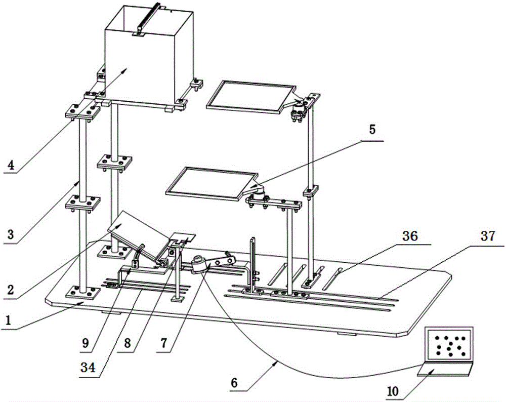
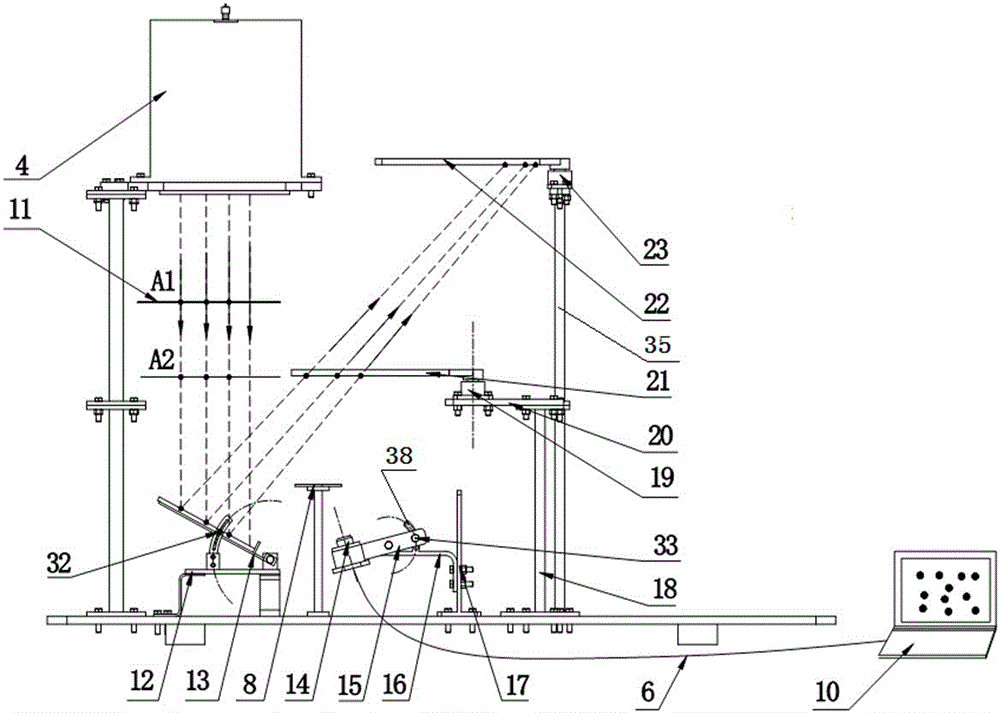
[0032] Such as figure 1 , figure 2 As shown, the detection device of the present invention includes a base 1, a light emitter 4, a transparent checkerboard target 11, a mirror regulator 9, a fixed checkerboard target 8, a camera collection device 7, a light receiving target 5, and a data processing terminal 10. The mirror adjuster 9 is installed on the base 1, the mirror 2 to be tested is installed on the mirror adjuster 9, a light emitter 4 is arranged directly above the mirror adjuster 9, and a light transmitter 4 is arranged between the light emitter 4 and the mirror 2 to be measured. Transparent checkerboard target 11, the surface of transparent checkerboard target 11 receiving light, and the surface of light receiving target 5 receiving light are all provided with black and white checkerboard patterns, and the upper side of mirror regulator 9 is ...


PUM


Abstract

The present invention discloses a solar concentrator reflection mirror shape detection device based on optical imaging. The device comprises a base, a light beam emitter, a transparent board target, a mirror surface adjuster, a fixed board target, an image capture device, a light receiving target and a data processing terminal. The mirror surface adjuster, the fixed board target and the image capture device are installed on the base. A mirror surface to be detected is installed on the mirror surface adjuster, and the light beam emitter is arranged above the mirror surface adjuster. The transparent board target is arranged between the light beam emitter and the mirror surface to be detected. Both the surfaces of the transparent board target and the light receiving target are provided with checkerboard patterns. The light receiving target is arranged above the mirror surface adjuster. The fixed board target is in the visual range of the image capture device. The image capture device is connected to the data processing terminal. According to the device, the mirror surface to be detected can be placed arbitrarily, the installation is convenient, and the application scope is very wide. The invention also discloses a solar concentrator reflection mirror shape detection method based on optical imaging.

Description

technical field [0001] The invention relates to the field of solar thermal power generation, in particular to a device and method for detecting the surface shape of a reflective mirror of a solar concentrator based on optical imaging. Background technique [0002] In the field of solar thermal utilization, especially in the field of solar thermal power generation technology, due to the low energy flow density of solar radiation resources, it is necessary to gather large areas of solar energy to achieve high-grade solar thermal utilization. The large-area concentration of solar energy is achieved by using a reflective mirror with high reflectivity. Because the heat sink device is far away from the reflective mirror of the concentrator, and there are certain errors in the manufacturing process of the reflective mirror, especially the reflection The normal error of the mirror surface, that is, the deviation angle between the normal direction of a certain point on the actual mir...

Claims


Application Information

Patent Timeline
Patent Type & Authority Applications(China)
IPC IPC(8): G01B11/24G01M11/00
Inventor 颜健彭佑多余佳焕
Owner HUNAN UNIV OF SCI & TECH
Why Eureka
Try Eureka