Eureka AIR delivers breakthrough ideas for toughest innovation challenges, trusted by R&D personnel around the world.

Conveyor beam

a conveyor beam and beam technology, applied in the direction of conveyors, structural elements, building components, etc., can solve the problems of inconvenient assembly of conveyor beams, inconvenient use of complete tools, and inability to manufacture straight conveyor beam parts, etc., to achieve the effect of high locking for

Active Publication Date: 2016-01-19
FLEXLINK
View PDF17 Cites 7 Cited by
  • Summary
  • Abstract
  • Description
  • Claims
  • Application Information

AI Technical Summary

Benefits of technology

[0011]By this first embodiment of the conveyor beam according to the invention, a conveyor beam comprising at least two conveyor beam elements, e.g. two split conveyor beams, can be assembled in a easy and reliable way. Since each connector element consists of one unitary part, preferably produced in one piece, the assembly of a conveyor beam by the use of the connector elements easy and cost-effective. The connector elements are simply inserted into longitudinal channels in the two conveyor beam elements that are to be interconnected and slid to the positions at which the interconnections should be located. At these positions, each connector element is rotated form the inserting position to the arresting position. The rotation of the connector element may be done by a wrench or a similar tool, or may be done by hand. During the rotation, the connector element will interact with the channels and will press against the inner sides of the channel with bearing surfaces of the connector element.
[0012]When a connector element is positioned and locked at the appropriate interconnection position, a new connector element can be inserted and positioned at a new interconnection position in the conveyor beam. In this way, a conveyor beam comprising two split conveyor beam elements is assembled in a fast and reliable way. This is advantageous in that both bends of different kinds and straight conveyor beams can be supplied in a cost-efficient way. The use of connector elements to assemble a conveyor beam is especially advantageous for conveyor bends. A conventional straight conveyor beam is produced by extruded aluminium. Such a beam is more or less impossible to bend, especially in a smaller radius. Instead, curved conveyor beams are assembled from two conveyor half beam elements. The use of a unitary connector element simplifies the assembly of a curved conveyor beam. It is also possible to assemble a wide conveyor beam from a central conveyor beam and two split conveyor beams by using a plurality of connector elements.
[0014]In an advantageous development of the invention, the bearing surfaces of the connector element is provided with protrusions that allow an even higher locking force between the connector element and the conveyor beam. The protrusions preferably provides for a self-locking action such that the connector element cannot rotate backwards without excessive force. In this way, vibrations induced in the conveyor track by the conveyor chain will not loosen the connector elements from the conveyor beam elements. Further, the protrusions preferably also provide an electrical contact between the conveyor beam elements and the connector element, such that all parts in the conveyor system can be grounded in a reliable way. The connector element is preferably provided with a key grip having four or six surfaces such that standard wrenches can be used when assembling the conveyor beam.
[0015]In an advantageous development of the invention, the conveyor beam comprises a third conveyor beam element attached to the conveyor beam by an attachment section of the connector element. The attachment section extends downwards from the central portion and secures the third conveyor beam element by a screw extending through a through-hole in the connector element. The third conveyor beam element is in one example a concealed conveyor chain return path, in which the return path of the conveyor chain is covered and thus protected from contamination from dust, liquids etc. The third conveyor beam element is preferably provided with inclined upper surfaces such that contaminating particles and the like do not stick to the upper surface.

Problems solved by technology

It is also possible to assemble a conveyor beam from beam segments for providing conveyor beam types that are produced in smaller numbers, where a complete tool is not cost efficient.
The conveyor beam parts that are not straight, such as horizontal and vertical bends, are difficult to manufacture from a single profile and are mostly assembled from pre-bent beam segments with a connecting beam clip assembly.
These and other known conveyor beams are interconnected with different connector elements consisting of several parts which leads to a relatively complicated and time consuming assembly of the conveyor beam.

Method used


Image

  • Conveyor beam
  • Conveyor beam
  • Conveyor beam

Examples


Embodiment Construction

[0023]The embodiments of the invention with further developments described in the following are to be regarded only as examples and are in no way to limit the scope of the protection provided by the patent claims.

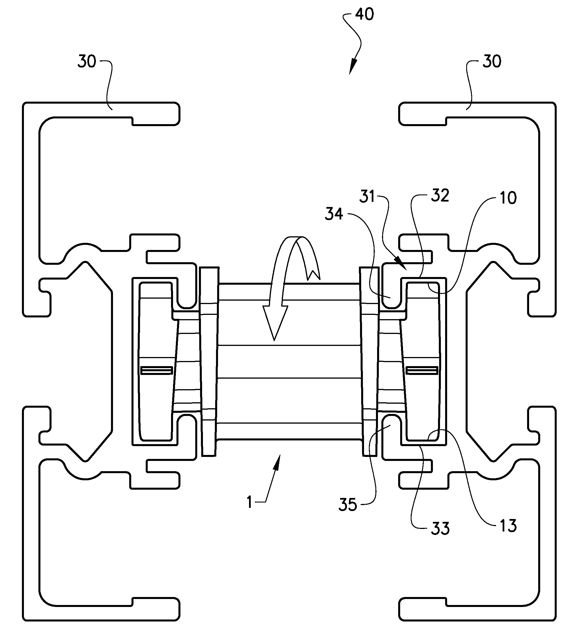
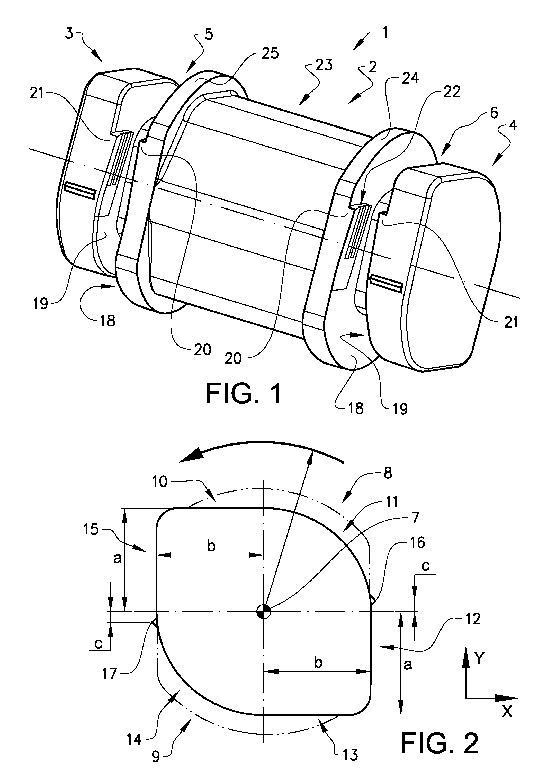
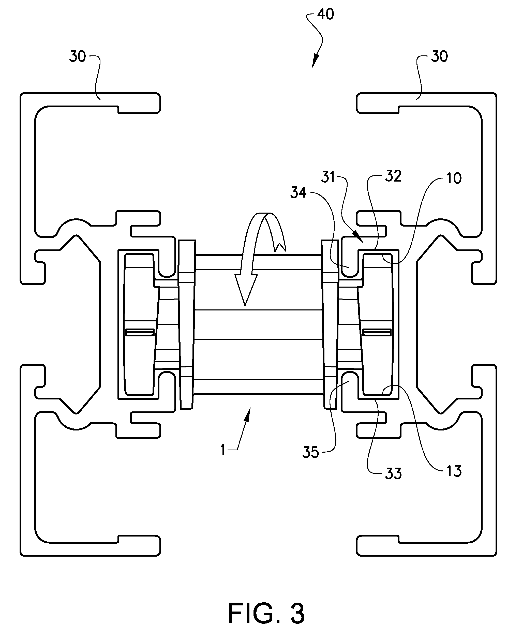
[0024]FIG. 1 shows a connector element for use in a conveyor beam according to the invention in a perspective view, and FIG. 2 shows an outer portion of the connector element in a side view. In the described example, the connector element 1 comprises a central portion 2 and two outer portions 3, 4, one on each side of the central portion. The central portion 2 and the first and the second outer portions are provided with the same central axis 7. A first groove 5 which extends peripherally around the connector element is provided between the central portion 2 and the first outer portion 3, and a second groove 6 which extends peripherally around the connector element is provided between the central portion 2 and the second outer portion 4. The central portion is provided with...


PUM


Abstract

Conveyor beam for a conveyor system, comprising a plurality of connector elements and at least two conveyor beam elements, where the connector element comprises a central portion, two outer portions and two peripherally grooves extending peripherally around the connector element between the central portion and the outer portions, where the connector element is provided with a first inserting position in which the connector element is inserted between two conveyor beam elements with the first outer portion positioned in a channel of a first conveyor beam element and the second outer portion positioned in a channel of a second conveyor beam elements, and a second arresting position, in which the connector element locks the conveyor beam elements together to form the conveyor beam. The advantage of the invention is that a conveyor beam of any desired shape can be obtained in an easy and fast way.

Description

PRIORITY CLAIM TO RELATED APPLICATIONS[0001]This application is a U.S. national stage application filed under 35 U.S.C. §371 from International Application Serial No. PCT / SE2013 / 050858, which was filed Jul. 3, 2013, and published as WO 2014 / 007747 on Jan. 9, 2014, and which claims priority to Sweden Application No. 1250762-0, filed Jul. 4, 2012, which applications and publication are incorporated by reference as if reproduced herein and made a part hereof in their entirety, and the benefit of priority of each of which is claimed herein.TECHNICAL FIELD[0002]The present invention relates to a conveyor beam comprising a plurality of unitary connector elements interconnecting two beam elements into a conveyor beam. Such a conveyor beam may comprise beam elements of different kinds, such as a split straight conveyor beam element, a plain bend element, an X-bend element or other conveyor beam elements.BACKGROUND ART[0003]Conveying devices, such as those which are used for moving objects b...

Claims


Application Information

Patent Timeline
Patent Type & Authority Patents(United States)
IPC IPC(8): B65G21/06F16B2/14F16B21/02E04C3/04
CPCB65G21/06F16B2/14F16B21/02E04C2003/0417E04C2003/0434E04C2003/0465E04B1/58
Inventor ASKERDAL, MAGNUSSALMI, MARKO
Owner FLEXLINK
Why Eureka
Eureka Blog
Learn More