
Air cleaner for vehicle

a technology for air cleaners and vehicles, applied in the direction of combustion-air/fuel-air treatment, separation processes, filtration separation, etc., can solve the problems of inconvenient replacement of elements, inability to properly perform filtering functions of air cleaners, and long replacement time, so as to prevent vibration noise, facilitate and convenient replacement, the effect of minimizing air leakag

Active Publication Date: 2016-02-09
LEEHAN CORP
View PDF11 Cites 7 Cited by
  • Summary
  • Abstract
  • Description
  • Claims
  • Application Information

AI Technical Summary

Benefits of technology

This design enables quick and convenient element replacement while preventing vibration noise and air leakage, ensuring effective filtration and reduced maintenance time.

Problems solved by technology

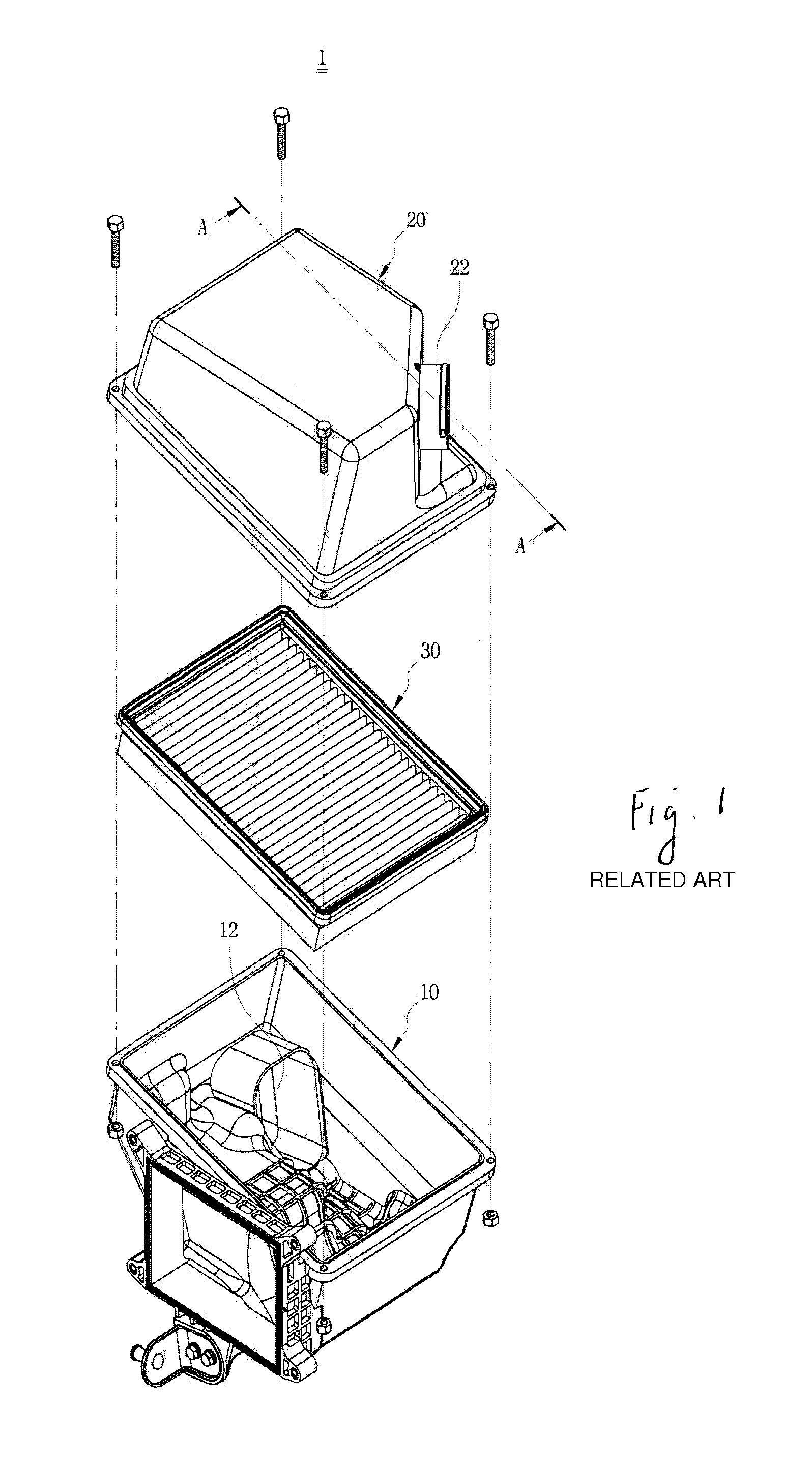
There is a problem in that when the air cleaner 1 is used for a long period of time, a large amount of impurities is attached to the element 30, and thereby, the air cleaner 1 does not properly perform a filtering function.
However, because the body portion 10 and the cover portion 20 of the air cleaner 1 in the related art are coupled to each other by bolts, the bolts, which fix four corners of the body portion 10 and the cover portion 20, needs to be removed to replace the element 30, and therefore, there are problems in that it is inconvenient to replace the element 30, and it takes a long time to replace the element 30.
However, the aforementioned technology has a merit in that the air cleaner 1 is mounted in an air cleaner housing so as to be detachable like a drawer structure such that the air cleaner 1 may be easily and conveniently replaced, but has a problem in that because an element is not securely fixed when flow pressure occurs in the housing, which causes vibrating noise.

Method used


Image

  • Air cleaner for vehicle
  • Air cleaner for vehicle
  • Air cleaner for vehicle

Examples


Embodiment Construction

[0027]Hereinafter, an air cleaner for a vehicle according to exemplary embodiments of the present disclosure will be described in more detail with reference to the drawings.

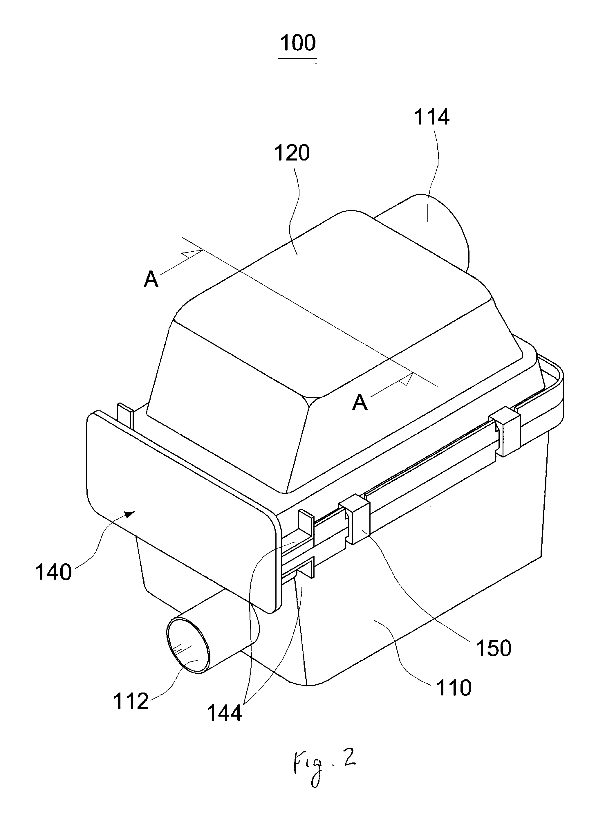
[0028]FIG. 2 is a view schematically illustrating an air cleaner for a vehicle according to an exemplary embodiment of the present disclosure, and FIG. 3 is an exploded perspective view of the air cleaner for a vehicle according to the exemplary embodiment of the present disclosure.

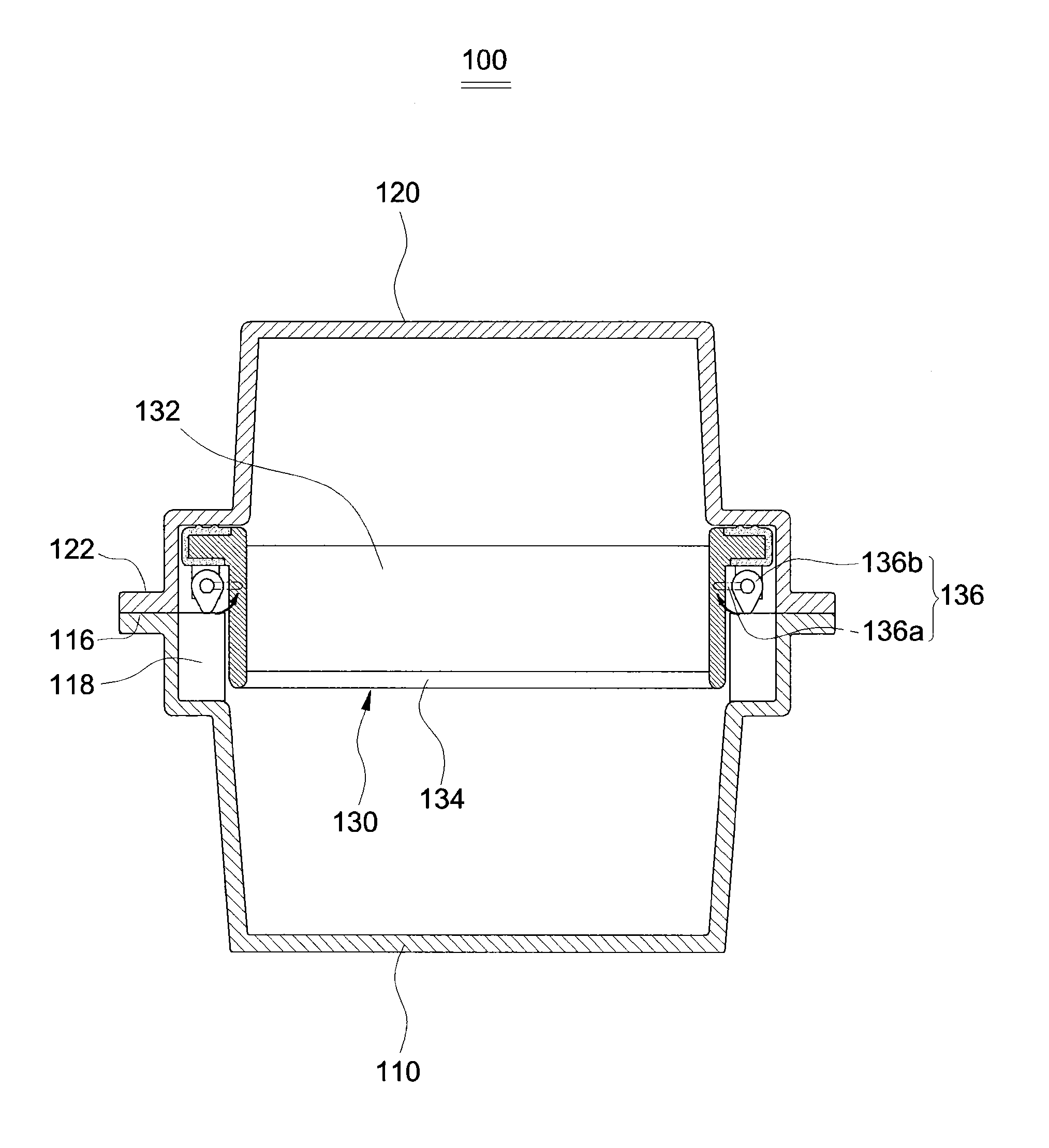
[0029]Referring to FIGS. 2 and 3, an air cleaner 100 for a vehicle according to an exemplary embodiment of the present disclosure may include a body portion 110 which has an air inlet 112 formed at one side of the body portion 110 so as to suck air, a cover portion 120 which is coupled to an upper portion of the body portion 110 and has an air outlet 114 formed at one side of the cover portion 120, an element 130 which is installed in the body portion 110 and the cover portion 120 so as to filter air, and an element cover 140 which is ...


PUM

PropertyMeasurementUnit
diameteraaaaaaaaaa
distanceaaaaaaaaaa
pressureaaaaaaaaaa

Abstract

Disclosed is an air cleaner for a vehicle. The air cleaner for a vehicle according to the exemplary embodiment includes: a body portion which has an air inlet formed at one side of the body portion so as to suck air; a cover portion which is coupled to an upper portion of the body portion and has an air outlet formed at one side of the cover portion; an element which is inserted into or withdrawn from the interior of the body portion and the cover portion through a receiving opening that is formed at one side of the body portion and the cover portion; a height adjustment handle which is rotatably coupled to a lower portion of the element and allows the element to be raised upward and lowered downward by a rotation of the height adjustment handle; and an element cover which is coupled to one side of the cover portion so as to prevent the element from being moved away from the receiving opening, and has a locking member which is provided at one surface of the element cover and has elastic force.

Description

CROSS-REFERENCE TO RELATED APPLICATION[0001]This application claims priority to and the benefit of Korean Patent Application No. 10-2013-0077430 filed in the Korean Intellectual Property Office on Jul. 2, 2013, the entire contents of which are incorporated herein by reference.TECHNICAL FIELD[0002]The present disclosure relates to an air cleaner for a vehicle, and more particularly, to an air cleaner for a vehicle capable of allowing an element, which is installed in the air cleaner, to be assembled like a drawer structure, and preventing the element from being shaken by flow pressure of air that flows in the air cleaner.BACKGROUND OF THE DISCLOSURE[0003]In general, a vehicle generates power by mixing fuel and air and combusting the mixture of fuel and air. That is, fuel stored in a fuel tank of a vehicle passes through various types of fuel supply devices, is mixed with air introduced from the outside, and then is injected into a cylinder of an engine, and at the same time, the engi...

Claims


Application Information

Patent Timeline
Patent Type & Authority Patents(United States)
IPC IPC(8): B01D46/00F02M35/02F02M35/024
CPCF02M35/0203F02M35/0245F02M35/02416F02M35/02491B01D27/02B01D27/08F02M35/024
Inventor CHO, CHEONGYONG
Owner LEEHAN CORP
Learn More