Electrophoretic display capable of reducing passive matrix coupling effect and method thereof

a technology of electrophoretic display and coupling effect, which is applied in the direction of static indicating devices, instruments, cathode-ray tube indicators, etc., can solve the problems of poor driving method of prior art for passive matrix panels, and achieve the effects of reducing coupling effect, coupling effect, and coupling

Active Publication Date: 2016-02-16
YUANHAN MATERIALS INC
View PDF21 Cites 124 Cited by
  • Summary
  • Abstract
  • Description
  • Claims
  • Application Information

AI Technical Summary

Benefits of technology

[0006]An embodiment provides an electrophoretic display capable of reducing passive matrix coupling effect. The electrophoretic display includes an electrophoretic panel, a plurality of first scan lines, and a plurality of second scan lines. The electrophoretic panel includes a plurality of pixels. Each pixel of the plurality of pixels corresponds to a storage capacitor, and the storage capacitor is coupled to a first scan line and a second scan line. When the pixel is used for displaying a first color, the first scan line receives a first driving voltage, the second scan line is coupled to ground, and other first scan lines and other second scan lines receive a first voltage. A voltage difference between the first driving voltage and the first voltage and a voltage difference between the first voltage and the ground are smaller than a first threshold value corresponding to the first color.
[0007]Another embodiment provides a method capable of reducing coupling effect of a passive matrix electrophoretic display, where the electrophoretic display includes an electrophoretic panel, a plurality of first scan lines, and a plurality of second scan lines, and the electrophoretic panel includes a plurality of pixels. The method includes inputting a driving voltage to a first scan line; coupling a second scan line corresponding to the first scan line to ground; inputting a voltage to other first scan lines and other second scan lines; and a pixel corresponding to the first scan line and the second scan line displaying a color according to a voltage difference between the driving voltage and the ground. The voltage difference between the driving voltage and the voltage and a voltage difference between the voltage and the ground are smaller than a threshold value corresponding to the color.
[0008]Another embodiment provides a method capable of reducing coupling effect of a passive matrix electrophoretic display, where the electrophoretic display includes an electrophoretic panel, a plurality of first scan lines, and a plurality of second scan lines. The method includes repeatedly inputting a corresponding driving voltage to each first scan line of the plurality of first scan lines a plurality of times in turn during a refresh frame time of the electrophoretic panel.
[0009]The present invention provides an electrophoretic display capable of reducing passive matrix coupling effect and a method thereof. The electrophoretic display and the method make a voltage difference received by a driven pixel is greater than a threshold value corresponding to a color displayed by the driven pixel, and make a voltage difference received by other pixels of the electrophoretic panel is smaller than the threshold value corresponding to the color displayed by the driven pixel, or make a corresponding driving voltage be repeatedly inputted to each first scan line of the plurality of first scan lines a plurality of times in turn during a refresh frame time of the electrophoretic panel. Thus, compared to the prior art, the present invention can reduce capacitor coupling effect of a plurality of pixels of the electrophoretic panel to make the plurality of pixels of the electrophoretic panel display correct colors.

Problems solved by technology

Therefore, the prior art is not a good driving method for the passive matrix panel.

Method used


Image

  • Electrophoretic display capable of reducing passive matrix coupling effect and method thereof
  • Electrophoretic display capable of reducing passive matrix coupling effect and method thereof
  • Electrophoretic display capable of reducing passive matrix coupling effect and method thereof

Examples


Embodiment Construction

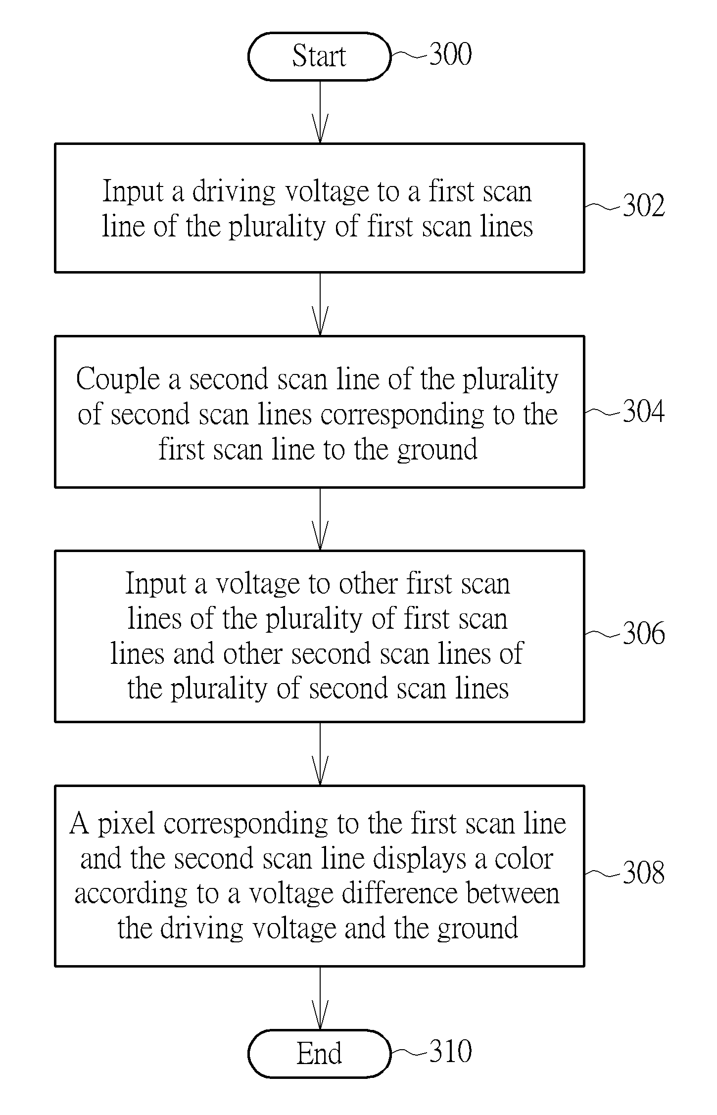
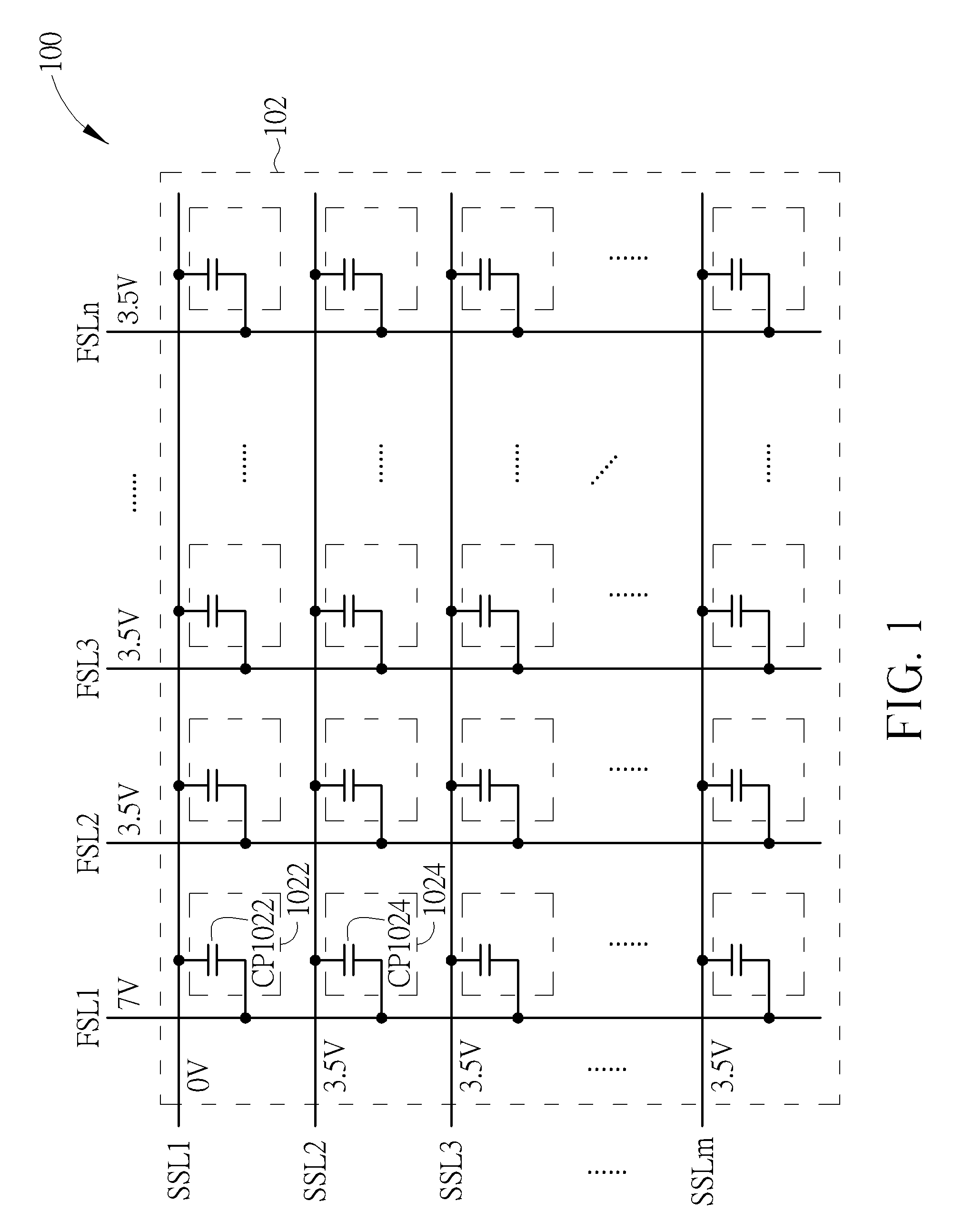
[0017]Please refer to FIG. 1. FIG. 1 is a diagram illustrating an electrophoretic display 100 capable of reducing passive matrix coupling effect according to an embodiment. As shown in FIG. 1, the electrophoretic display 100 includes an electrophoretic panel 102, a plurality of first scan lines FSL1-FSLn, and a plurality of second scan lines SSL1-FSLm, where n, m are integers. As shown in FIG. 1, the electrophoretic panel 102 has a first axis direction (e.g. a vertical direction) and a second axis direction (e.g. a horizontal direction), where the plurality of first scan lines FSL1-FSLn are installed on the first axis direction, and the plurality of second scan lines SSL1-FSLm are installed on the second axis direction. The electrophoretic panel 102 includes a plurality of pixels. Each pixel of the plurality of pixels of the electrophoretic panel 102 corresponds to a storage capacitor, and the storage capacitor is coupled to a first scan line of the plurality of first scan lines FSL...


PUM


Abstract

An electrophoretic display capable of reducing passive matrix coupling effect includes an electrophoretic panel, a plurality of first scan lines, and a plurality of second scan lines. The electrophoretic panel includes a plurality of pixels. Each pixel of the plurality of pixels corresponds to a storage capacitor, and the storage capacitor is coupled to a first scan line and a second scan line. When the pixel is used for displaying a first color, the first scan line receives a first driving voltage, the second scan line is coupled to ground, and other first scan lines and other second scan lines receive a first voltage. A voltage difference between the first driving voltage and the first voltage and a voltage difference between the ground and the first voltage are smaller than a first threshold value corresponding to the first color.

Description

BACKGROUND OF THE INVENTION[0001]1. Field of the Invention[0002]The present invention relates to an electrophoretic display capable of reducing passive matrix coupling effect and a method thereof, and particularly to an electrophoretic display capable of reducing passive matrix coupling effect and a method thereof that can reduce capacitor coupling effect of a plurality of pixels of the electrophoretic panel to make the plurality of pixels of the electrophoretic panel display correct color.[0003]2. Description of the Prior Art[0004]In the prior art, when a pixel (P) of a passive matrix panel (e.g. an electrophoretic panel) is driven to display a first color (e.g. black color), a first scan line coupled to the pixel (P) is used for receiving a first driving voltage (e.g. 7V), a second scan line coupled to the pixel (P) is used for receiving a second driving voltage (e.g. 0V), and other first scan lines and other second scan lines of the passive matrix panel are floating, where the fi...

Claims


Application Information

Patent Timeline
Patent Type & Authority Patents(United States)
IPC IPC(8): G09G5/10G09G3/34
CPCG09G3/344G09G2310/0267
Inventor WU, YAN-LIANGHUNG, CHI-MAOSUN, WEI-MINTIEN, PEI-LINHSU, CHIH-YUANCHENG, HSIAO-LUNG
Owner YUANHAN MATERIALS INC
Why Eureka
Try Eureka