
Operating element device

a technology of operating element and operating device, which is applied in the direction of instruments, electrophonic musical instruments, strings of musical instruments, etc., can solve the problem that the keyboard apparatus cannot provide a player with a clear click feeling, and achieve the effect of facilitating the manufacturing of reaction force generation, facilitating the operation of favorable feeling in the operation of the operating element device, and simplifying the reaction force generation member

Active Publication Date: 2016-02-23
YAMAHA CORP
View PDF15 Cites 9 Cited by
  • Summary
  • Abstract
  • Description
  • Claims
  • Application Information

AI Technical Summary

Benefits of technology

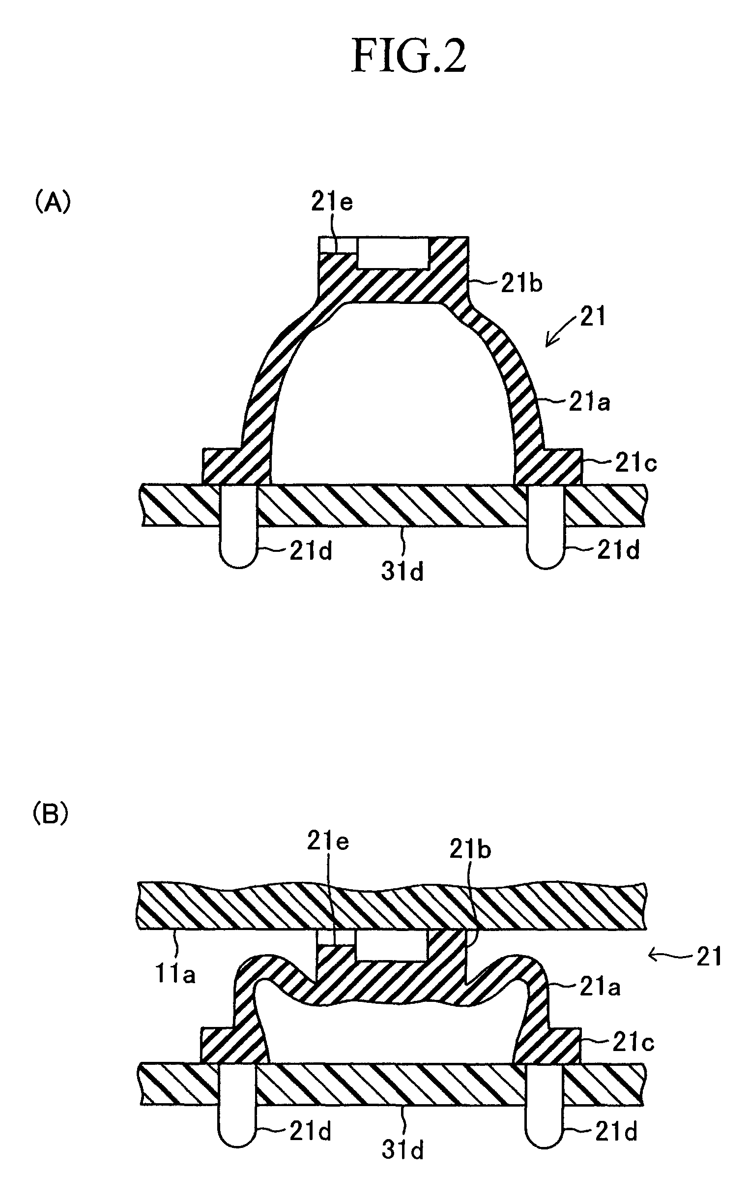
[0007]The keyboard apparatus has the key 91 which is to be depressed and released by a player, and the reaction force generation member 92 which exerts a reaction force against a player's depression of the key 91. At the rear end of the key 91, the key 91 is supported by a key supporting portion 94 erected on the rear end of a key frame 93 having a horizontal top portion so that the front end of the key 91 can pivot up and down. The center of the pivot of the key 91 is defined as a pivot axis C. The reaction force generation member 92 is fastened to the upper surface of the key frame 93 such that the reaction force generation member 92 is situated below the depression portion 91a which is located at a central portion in the front-rear direction of the key 91 and has a flat undersurface. The reaction force generation member 92 is integrally formed of an elastic member such as rubber to have a dome-shaped thin body portion 92a and a cylindrical top portion 92b having a flat upper surface. The central axis line extending in the vertical direction of the reaction force generation member 92 is defined as an axis line Y1. Between the key 91 and the key frame 93, a spring 95 is provided which urges the key 91 upward such that the spring 95 is situated at a middle position between the reaction force generation member 92 and the key supporting portion 94. The front end of the key 91 extends downward. At the lower end of the front end of the key 91, an engagement portion 91b jutting rearward is provided so that the engagement portion 91b is inserted through a through-hole provided on the key frame 93 from the front toward the rear beneath the key frame 93. On the undersurface of the front end of the key frame 93, a stopper member 96 is provided so that the contact between the stopper member 96 and the engagement portion 91b of the key 91 can restrict upward displacement of the front end of the key 91.
[0023]Furthermore, the reaction force generation member may be further provided with a base portion (22c) which is located beneath the elastically deformable portion and is rarely elastically deformable by load such that the base portion is fastened to a mounting surface to fasten the reaction force generation member to the mounting surface, while a thickness of the base portion is varied according to position thereof to allow the axis line direction of the reaction force generation member to incline against a normal line of the mounting surface. In this case, for example, a normal direction of an upper surface of the base portion of the reaction force generation member is parallel to the axis line of the reaction force generation member. Furthermore, the reaction force generation member may be fastened to the mounting surface inclined against the depression surface of the depression portion in a state where the operating element device is not being operated by the operator. By such a configuration, the axis line direction of the reaction force generation member can be easily inclined against the mounting surface.

Problems solved by technology

However, the above-described conventional keyboard apparatus has a problem that the keyboard apparatus cannot provide a player with a clear feeling of click because the whole circumference of the reaction force generation member cannot buckle at one time in response to a depression of a key.

Method used


Image

  • Operating element device
  • Operating element device
  • Operating element device

Examples


first embodiment

a. First Embodiment

a1. First Example

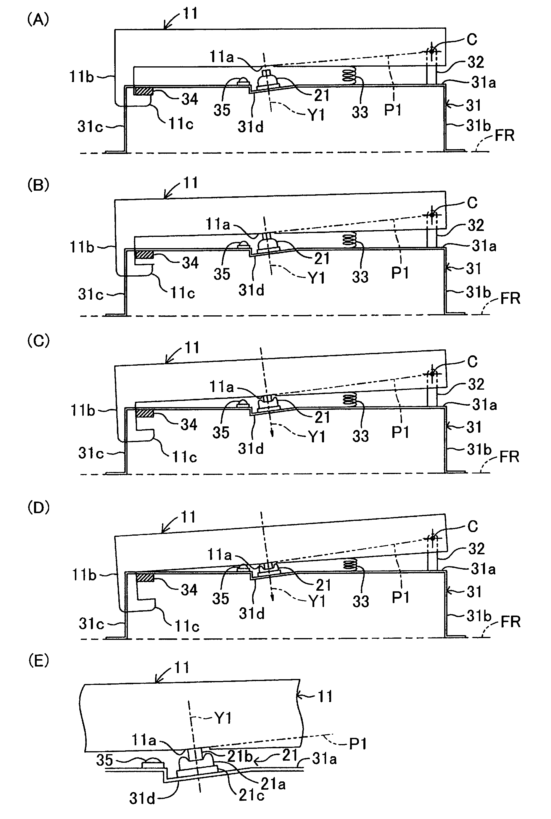
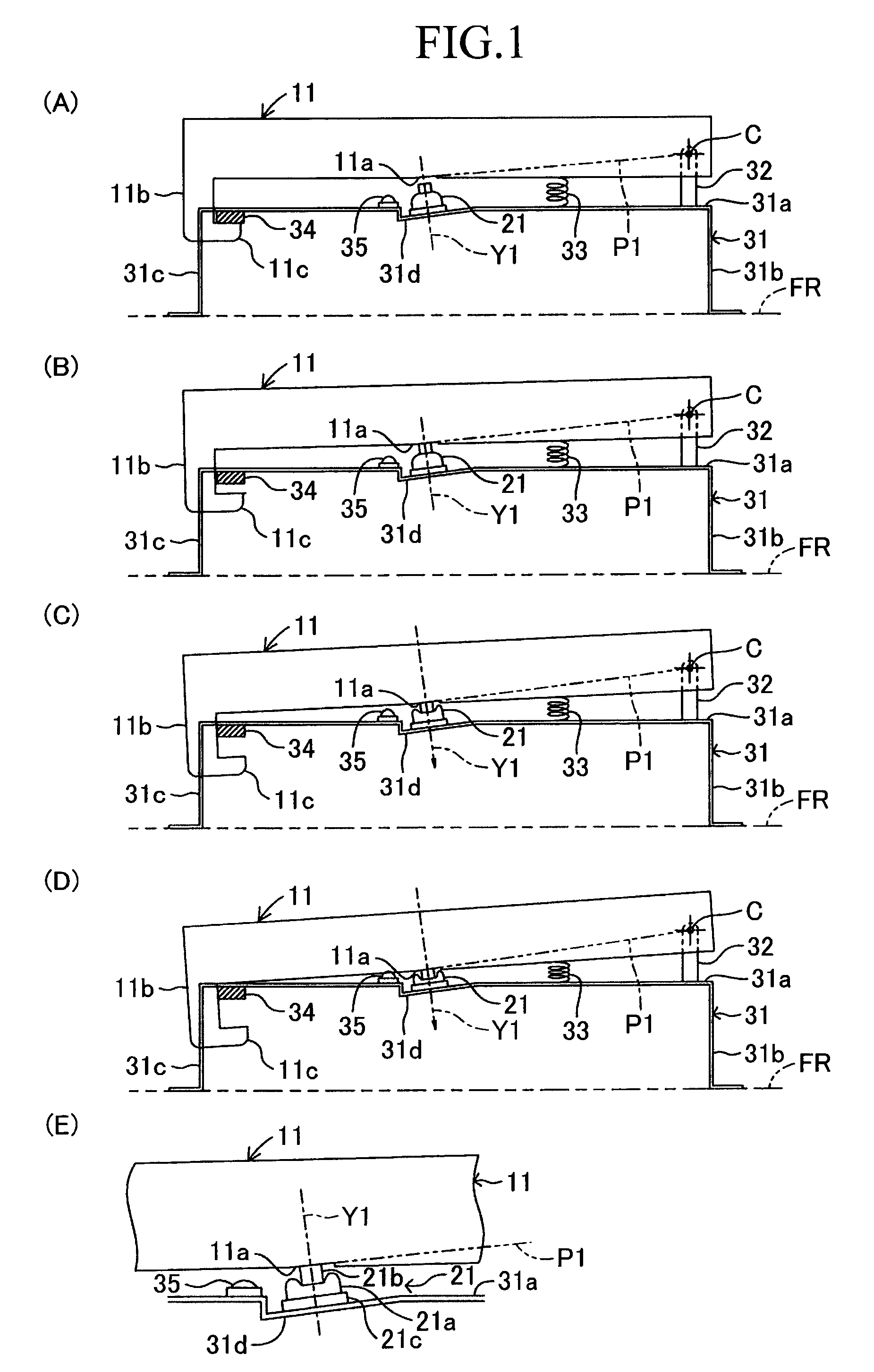
[0045]The first example of the first embodiment of the present invention will now be described with reference to the drawings. FIG. 1(A) to (D) are schematic side views each indicative of a keyboard apparatus according to the first example seen from the right. The keyboard apparatus has a key 11 which a player depresses and releases, and a reaction force generation member 21 which exerts a reaction force in response to the player's depression of the key 11. In this case, more specifically, FIG. 1(A) indicates the keyboard apparatus in a state where the key 11 is being released and has not been depressed yet. FIG. 1(B) indicates the keyboard apparatus in a state where the key 11 has been depressed, so that a depression portion of the key has started coming into contact with the upper end of the reaction force generation member 21. FIG. 1(C) indicates the keyboard apparatus in a state where the key 11 has been depressed further, so that the reaction...

first modification

a4. First Modification

[0075]Next, the first modification of the first embodiment will be explained with reference to FIG. 7. FIG. 7(A) is a side view in which the keyboard apparatus whose key 11 is being released (before start of a key-depression) is seen from the right. FIG. 7(B) is a side view in which the keyboard apparatus in a state where the key 11 had been depressed, so that the depression portion 11a of the key has started coming into contact with the upper end of the reaction force generation member 22 is seen from the right. FIG. 7(C) is a side view in which the keyboard apparatus in a state where the key 11 had been depressed further, so that the reaction force has reached its peak immediately before the reaction force generation member 21 buckles is seen from the right. FIG. 7(D) is an enlarged view of the reaction force generation member 22 of FIG. 7(C). In this modification as well, similarly to the second example, the reaction force generation member 22 has the body p...

second modification

a5. Second Modification

[0081]Next, the second modification of the first embodiment will be explained with reference to drawings. FIG. 8(A) is a side view in which the keyboard apparatus whose key 11 is being released (before start of a key-depression) is seen from the right. FIG. 8(B) is a side view in which the keyboard apparatus in a state where the key 11 had been depressed, so that the depression portion 11a of the key 11 has started coming into contact with the upper end of the reaction force generation member 22 is seen from the right. FIG. 8(C) is a side view in which the keyboard apparatus in a state where the key had been depressed further, so that the reaction force has reached its peak immediately before the buckling of the reaction force generation member 22 is seen from the right. FIG. 8(D) is an enlarged view of the reaction force generation member 22 of FIG. 8(C). In this modification as well, similarly to the second example, the reaction force generation member 22 ha...


PUM


Abstract

A key (11) is supported by key supporting portions (32) so that the key (11) can pivot. A reaction force generation member (22) is shaped like a dome to be elastically deformed by a key-depression of the key (11). At the time of the elastic deformation, the reaction force generation member (22) increases a reaction force from the beginning with an increasing amount of elastic deformation. After the reaction force reaches its peak, the reaction force generation member (22) buckles to reduce the reaction force. A normal line of a plane (P1) including a pivot axis (C) of the key (11) and a depression point of a depression portion (11a) is designed to be roughly parallel to an axis line (Y1) of the reaction force generation member (22) at the point in time when the reaction force of the reaction force generation member (22) reaches its peak.

Description

BACKGROUND OF THE INVENTION[0001]1. Field of the Invention[0002]The present invention relates to an operating element device having a reaction force generation member for generating a reaction force by elastically deforming in response to a operator's operation.[0003]2. Description of the Related Art[0004]Conventionally, there are keyboard musical instruments such as electronic organs and electronic pianos having reaction force generation members for exerting a reaction force against a depression of a key. For example, Japanese Examined Utility Model Application Publication No. 7-49512 discloses a keyboard apparatus having a reaction force generation member (let-off element) on a key frame (shelf board) which supports a key located above the key frame so that the key can pivot. The reaction force generation member is elastically deformed, by being depressed by the key depressed by a player, to generate a reaction force. Particularly, the reaction force generation member generates a ...

Claims


Application Information

Patent Timeline
Patent Type & Authority Patents(United States)
IPC IPC(8): G10C3/12G10H1/34
CPCG10C3/12G10H1/346
Inventor OSUGA, ICHIROHARIMOTO, HIROSHI
Owner YAMAHA CORP
Learn More