Constant velocity joint and assembly method therefor

a constant velocity joint and assembly method technology, applied in the direction of yielding couplings, couplings, rotary machine parts, etc., can solve the problems of difficult to efficiently assemble the constant velocity joints, hinder the insertion of the transmission shaft into the shaft hole, etc., and achieve the effect of efficient insertion and fitting

Active Publication Date: 2021-11-02
HONDA MOTOR CO LTD
View PDF7 Cites 0 Cited by
  • Summary
  • Abstract
  • Description
  • Claims
  • Application Information

AI Technical Summary

Benefits of technology

[0004]Incidentally, a so-called tripod type constant velocity joint is known, which transmits torque between an outer member and an inner member via annularly shaped spherical rollers. In this type of constant velocity joint, in order to increase transmittable torque, it may be considered to increase the diameter of the spherical rollers.
[0007]A principal object of the present invention is to provide a constant velocity joint, which can be assembled in an efficient manner even if the diameter of the spherical rollers is increased.
[0011]According to the present invention, when the spherical rollers are disposed at an innermost location inside the cylindrical portion so that the axial directions of the spherical rollers are perpendicular to the axial direction of the cylindrical portion, at least a part of the first inner bottom wall portion abuts against the inner side outer circumferential surface, and the second inner bottom wall portion is separated away from the outer side outer circumferential surface. In this case, the spherical rollers are easily inclined in directions in which the outer side outer circumferential surface portions are in close proximity to the second inner bottom wall portion, or stated otherwise, in directions in which the end portions (opening side end portions) facing toward the opening of the outer member separate away from the axis of the shaft hole of the inner member. Consequently, since the opening side end portions of the spherical rollers can be prevented from coming into proximity to the axis of the shaft hole and blocking the shaft hole, the transmission shaft can be efficiently inserted and fitted into the shaft hole. Stated otherwise, even if the diameter of the spherical rollers is increased, the constant velocity joint can be assembled in an efficient manner.

Problems solved by technology

When portions of the shaft hole are blocked by the spherical rollers, a concern arises in that insertion of the transmission shaft into the shaft hole is hindered, and it becomes difficult to efficiently assemble the constant velocity joint.

Method used


Image

  • Constant velocity joint and assembly method therefor
  • Constant velocity joint and assembly method therefor
  • Constant velocity joint and assembly method therefor

Examples


Embodiment Construction

[0022]A preferred embodiment of a constant velocity joint and a method of assembling the same according to the present invention will be presented and described in detail below with reference to the accompanying drawings. In the drawings referred to below, constituent elements that exhibit the same or similar functions and effects are denoted with the same reference characters, and repeated description of such features is omitted.

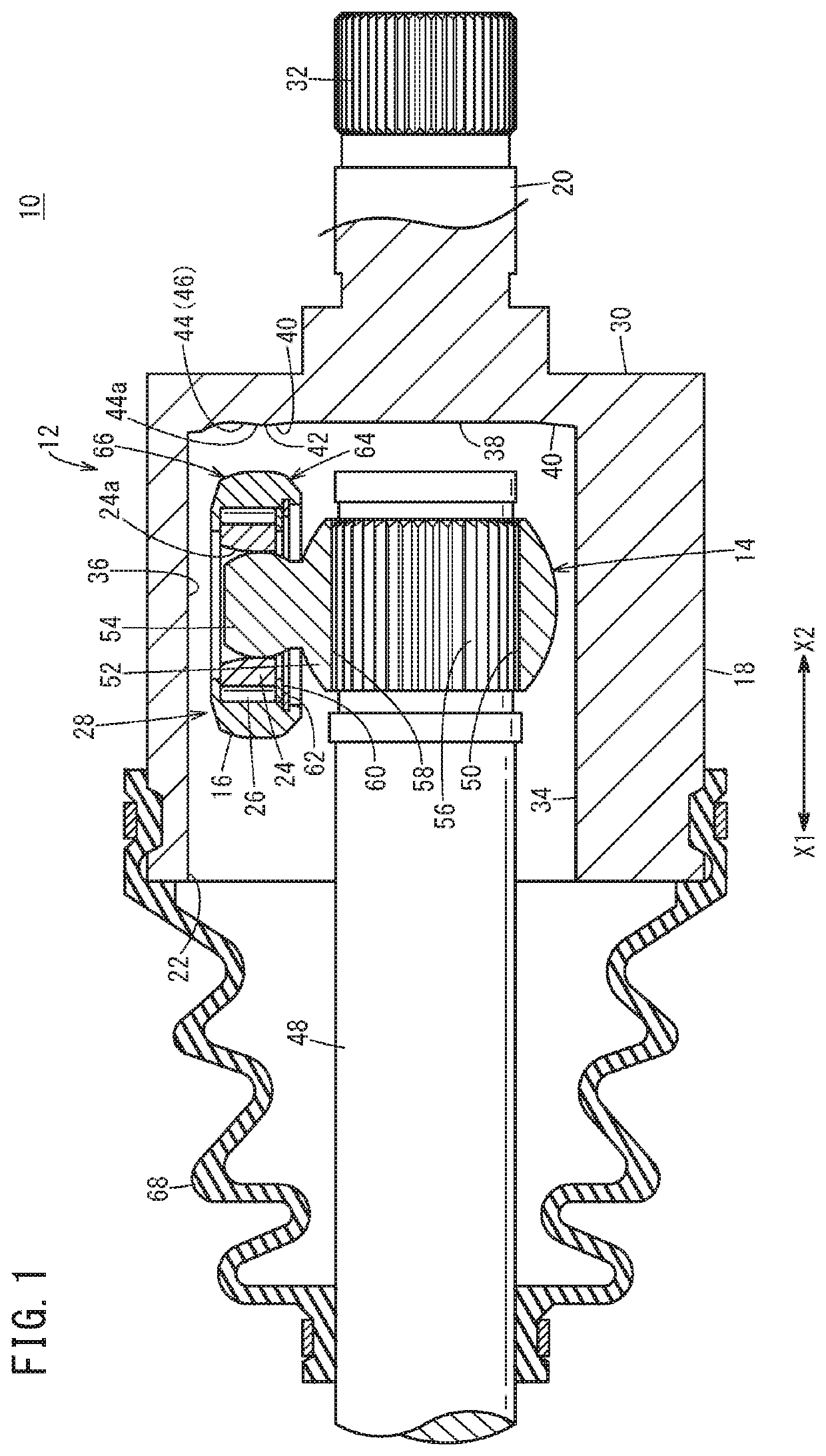
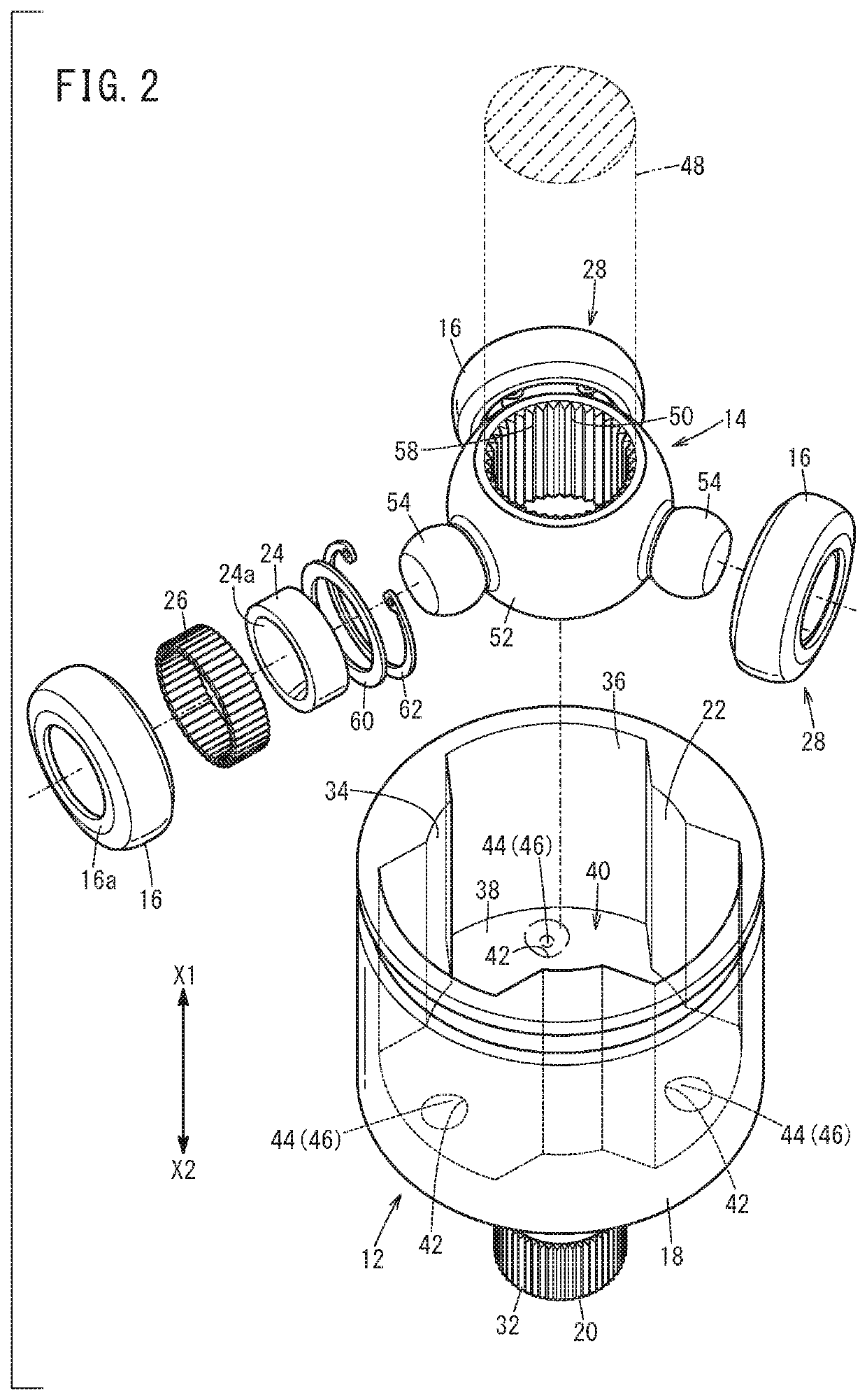
[0023]As shown in FIG. 1, a constant velocity joint 10 is equipped with an outer member 12, an inner member 14, and spherical rollers 16 that transmit torque between the outer member 12 and the inner member 14. The outer member 12 includes a cylindrical portion 18 and a shaft member 20. The cylindrical portion 18 is obtained, for example, by machining a metal material into a bottomed cylindrical shape, and an opening 22 is provided on one end side (the side of the arrow X1) thereof. The inner member 14 and the spherical rollers 16 are provided inside the cy...


PUM

PropertyMeasurementUnit
velocityaaaaaaaaaa
constant velocityaaaaaaaaaa
outer diameteraaaaaaaaaa

Abstract

A constant velocity joint includes spherical rollers. At least parts of first inner bottom wall portions provided on an inner bottom wall surface of a cylindrical portion of the constant velocity joint are located in closer proximity to the side of an opening of the cylindrical portion than second inner bottom wall portions. When the spherical rollers are disposed at an innermost location inside the cylindrical portion and the axial directions of the spherical rollers are perpendicular to the axial direction of the cylindrical portion, at least parts of the first inner bottom wall portions abut against inner side outer circumferential surface portions of the spherical rollers, and the second inner bottom wall portions are separated away from outer side outer circumferential surface portions of the spherical rollers.

Description

CROSS-REFERENCE TO RELATED APPLICATION[0001]This application is based upon and claims the benefit of priority from Japanese Patent Application No. 2018-216244 filed on Nov. 19, 2018, the contents of which are incorporated herein by reference.BACKGROUND OF THE INVENTIONField of the Invention[0002]The present invention relates to a constant velocity joint which is equipped with spherical rollers that transmit torque between an outer member and an inner member, as well as to a method of assembling such a constant velocity joint.Description of the Related Art[0003]For example, in Japanese Laid-Open Patent Publication No. 2008-089148, a method is disclosed of assembling a so-called cross-groove type constant velocity joint, in which torque is transmitted between an outer member and an inner member through a plurality of balls. In such an assembly method, first, the inner member in which a shaft hole and ball grooves are provided, and balls that are retained in the ball grooves via a reta...

Claims


Application Information

Patent Timeline
Patent Type & Authority Patents(United States)
IPC IPC(8): F16D3/06F16D3/10F16D3/223
CPCF16D3/06F16D3/10F16D3/223F16D2003/22313F16D2250/0084Y10S464/905Y10T29/49826F16D3/2055F16D2001/103F16D2003/2026
Inventor BONO, YASUHARUSAKAKIBARA, TAISUKESASAKI, TAICHIYOSHIDA, JUNJI
Owner HONDA MOTOR CO LTD
Why Eureka
Try Eureka