Combined permanent magnet eddy current speed governor

A permanent magnet eddy current and governor technology, applied in electrical components, electromechanical devices, electromechanical transmission devices, etc., can solve the problems of bearing life impact, wiping disks, damaged equipment, etc., achieving high safety, long service life, reducing The effect of vibration interference

Inactive Publication Date: 2014-12-31
北京必可测科技股份有限公司
View PDF6 Cites 4 Cited by
  • Summary
  • Abstract
  • Description
  • Claims
  • Application Information

AI Technical Summary

Problems solved by technology

The permanent magnet of the permanent magnet governor with cylindrical structure adopts radial magnetization, and the conductor rotor cuts the magnetic force line in the radial direction along the circumference, and the speed regulation is realized by adjusting the axial relative position of the permanent magnet and the copper conductor. The magnetic force direction is radial The axial force is very small, so a certain amount of movement in the axial direction is allowed, which has no effect on the motor and load bearings; the permanent magnet of the permanent magnet governor of the disc structure is magnetized in the axial direction, and the conductor rotor cuts the magnetic force line on the end face, and passes through Adjust the axial gap between the permanent magnet and the copper conductor to achieve speed regulation. The direction of the magnetic force is axial, so the axial force is relatively large, which must be borne by the motor and the bearing of the load, which has a certain impact on the life of the bearing. In severe cases, friction will occur. Disk phenomenon, damage equipment

Method used


Image

  • Combined permanent magnet eddy current speed governor
  • Combined permanent magnet eddy current speed governor
  • Combined permanent magnet eddy current speed governor

Examples


Embodiment Construction

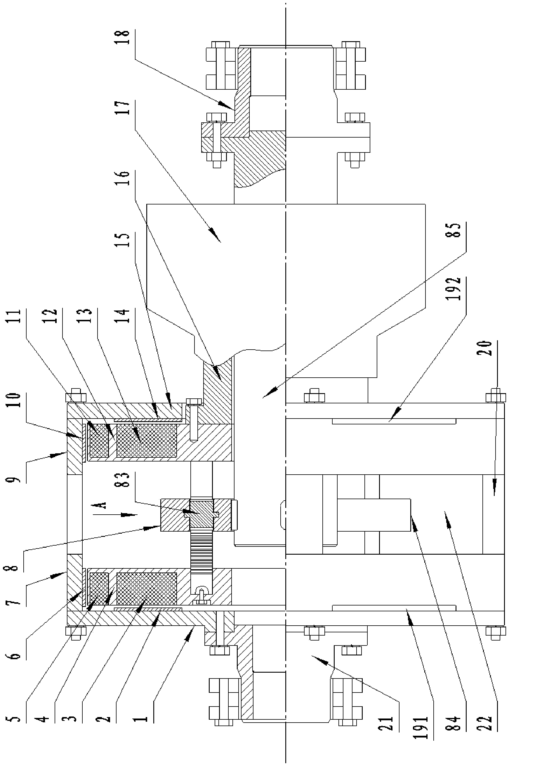
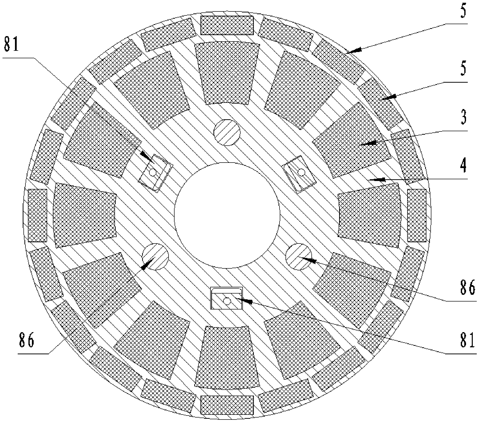
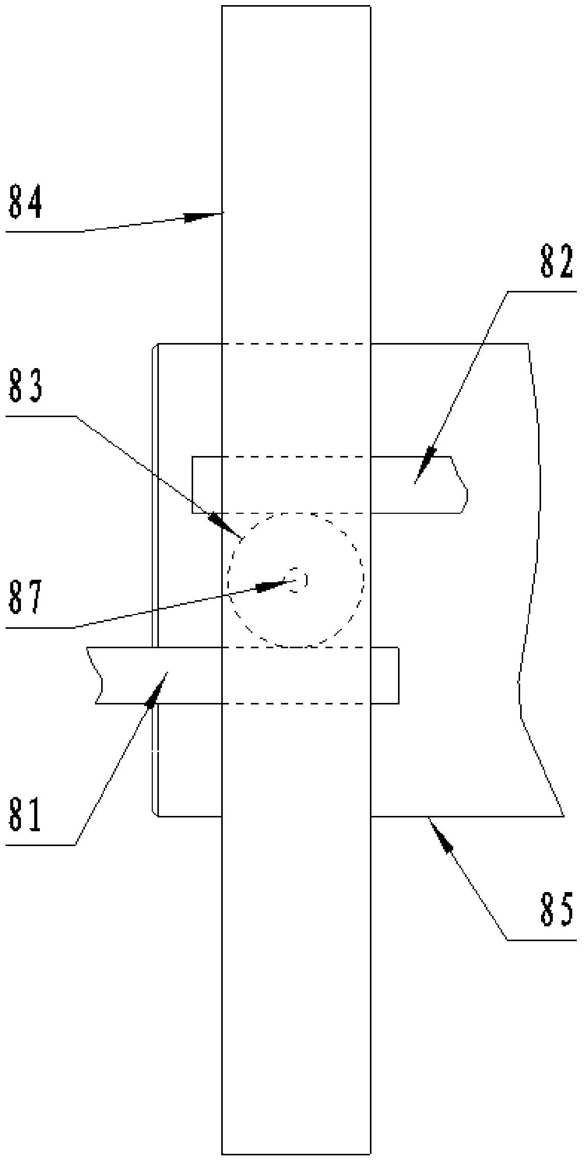
[0029] The composite permanent magnet eddy current governor of the present invention will be further described in detail below in conjunction with the accompanying drawings. A compound permanent magnet eddy current governor, comprising a conductor rotor and a permanent magnet rotor, the conductor rotor comprises a circumferential fixed sleeve, and the two ends of the circumferential fixed sleeve are respectively fixedly connected with a first conductor support disc and a second conductor support Disk, the inner surface of the first conductor supporting disk is provided with a first end surface conductor, the inner surface of the second conductor supporting disk is provided with a second end surface conductor, the inner surface of the circumferential fixed sleeve is provided with a radial conductor; the permanent magnet rotor It includes a first magnet mounting plate and a second magnet mounting plate parallel to each other, the edge area of ​​the first magnet mounting plate is ...


PUM


Abstract

The invention provides a combined permanent magnet eddy current speed governor which comprises a conductor rotor and a permanent magnet rotor, wherein the conductor rotor comprises a circumferential fixing sleeve, a first conductor supporting disk (1) and a second conductor supporting disk (15), wherein a first end face conductor (2) is arranged on the inner surface of the first conductor supporting disk (1), and a second end face conductor (14) is arranged on the inner surface of the second conductor supporting disk (15); a radial conductor is arranged on the inner surface of the circumferential fixing sleeve; the permanent magnet rotor comprises a first magnet mounting disk (4) and a second magnet mounting disk (12) which are parallel to each other; end face permanent magnets and radial permanent magnets are arranged on both the first magnet mounting disk (4) and the second magnet mounting disk (12). The combined permanent magnet eddy current speed governor combines a cylinder type structure with a disk type structure, the permanent magnets are simultaneously magnetized in the radial direction and the axial direction, and a copper conductor cuts magnetic lines of force in the radial direction and on the end face to increase electromagnetic damping. Output torque can be easily regulated by a regulating mechanism, and transmission power is greatly increased.

Description

technical field [0001] The invention relates to the technical field of permanent magnet transmission equipment, in particular to a composite permanent magnet eddy current governor. Background technique [0002] The compound permanent magnet eddy current governor is a new type of transmission connection system, and its technology was introduced from abroad in 2007. Its structure is mainly composed of three parts: conductor rotor, permanent magnet rotor and controller. The conductor rotor is fixed on the motor shaft, the permanent magnet rotor is fixed on the load shaft, and there is a gap (called air gap) between the conductor rotor and the permanent magnet rotor. In this way, the motor and the load are changed from the original hard (mechanical) connection to a soft (magnetic) connection. By adjusting the air gap between the permanent magnet and the copper conductor, the output torque on the load shaft can be changed, thereby realizing the change of the load speed. The air...

Claims


Application Information

Patent Timeline
Patent Type & Authority Applications(China)
IPC IPC(8): H02K51/00
Inventor 黄俊飞成国良
Owner 北京必可测科技股份有限公司
Why Eureka
Try Eureka