Plug for vehicle

a technology for plugs and vehicles, applied in the direction of functional valve types, gearing details, couplings, etc., can solve the problems of plugs easily falling out of through holes, plugs may easily fall out with respect, and the retaining lug margin is reduced

Active Publication Date: 2019-06-11
TOYOTA JIDOSHA KK
View PDF12 Cites 0 Cited by
  • Summary
  • Abstract
  • Description
  • Claims
  • Application Information

AI Technical Summary

Benefits of technology

[0004]In the meantime, like the breather device disclosed in JP 2008-180313 A, the hose may be connected to the plug. In such a case, the plug may rotate around its axial center due to application of an external force to the hose, or the like reason. In this regard, it is conceivable that a flange portion having a notch for prevention of rotation on its outer periphery is provided in a part of the plug, the part being not inserted into the through-hole, so that the rotation of the plug around the axial center is restricted by the notch and a projecting member provided in the housing at a position adjacent to the plug so as to project outside the housing. Meanwhile, depending on a configuration of the insertion portion provided with the retaining lug, the plug may easily fall out with respect to an external force applied to the plug. Particularly, in a case of the plug provided with the notch for prevention of rotation, when an external force is applied to the plug so as to incline the plug in an opposite direction to the notch, the plug is easily inclined, so that a hook margin of the retaining lug is reduced, which may cause the plug to easily fall out of the through-hole.
[0007]In the above aspect, the insertion portions are formed at the two positions opposed to each other across the straight line passing through the notch and the axial center and are provided with retaining lugs engageable with the through-hole. Accordingly, when the plug for the vehicle is inclined due to an external force in a direction opposite to the notch in which direction the plug for the vehicle is easily inclined, hook margins of the retaining lugs are hardly reduced. That is, by providing the retaining lugs at the positions where the hook margins of the retaining lugs are not reduced at the time when the plug for the vehicle is inclined due to the external force, it is possible to restrain the plug for the vehicle from falling out. Accordingly, in a case where the plug for the vehicle includes the flange portion provided with the notch that restricts the rotation around the axial center, even if the plug for the vehicle is inclined due to the external force, the plug for the vehicle can hardly fall out of the through-hole.
[0009]Further, in the above configuration, the insertion portions are further formed at the two positions opposed to each other across the axial center, on the straight line passing through the notch and the axial center, which allows the plug for the vehicle to be easily inserted straight into the through-hole at the time when the plug for the vehicle is inserted into the through-hole. Further, since the insertion portions formed at the two positions opposed to each other across the axial center are not provided with the retaining lugs, the plug for the vehicle is easily inserted into the through-hole. That is, when the retaining lugs are provided only at the positions where the hook margins of the retaining lugs are not reduced at the time when the plug for the vehicle is inclined due to the external force, it is possible to achieve both restraint of falling-off of the plug for the vehicle and easiness of the insertion thereof.
[0011]Further, in the above configuration, the flange portion is configured such that an arc where the notch is formed has a sector shape with an arc smaller than a semicircle, and therefore, it is useful to provide the retaining lugs at positions where the hook margins of the retaining lugs are not reduced at the time when the plug for the vehicle is inclined due to an external force in a direction opposite to the notch in which direction the plug is easily inclined.
[0013]Further, in the above configuration, the plug for the vehicle is a breather plug provided with the hose joint portion, and therefore, in a case where the breather plug includes the flange portion having the notch that restricts the rotation around the axial center, which might occur due to application of an external force to the hose, or the like reason, even if the breather plug is inclined due to the external force, the breather plug can hardly fall out of the through-hole.

Problems solved by technology

Meanwhile, depending on a configuration of the insertion portion provided with the retaining lug, the plug may easily fall out with respect to an external force applied to the plug.
Particularly, in a case of the plug provided with the notch for prevention of rotation, when an external force is applied to the plug so as to incline the plug in an opposite direction to the notch, the plug is easily inclined, so that a hook margin of the retaining lug is reduced, which may cause the plug to easily fall out of the through-hole.

Method used


Image

  • Plug for vehicle
  • Plug for vehicle
  • Plug for vehicle

Examples


Embodiment Construction

[0022]An embodiment of the present disclosure will hereinafter be described in detail with reference to the drawings.

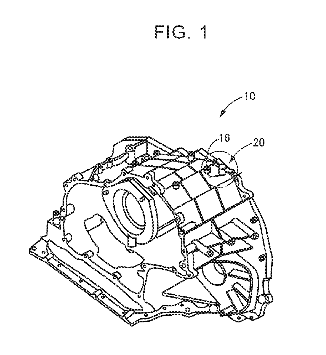
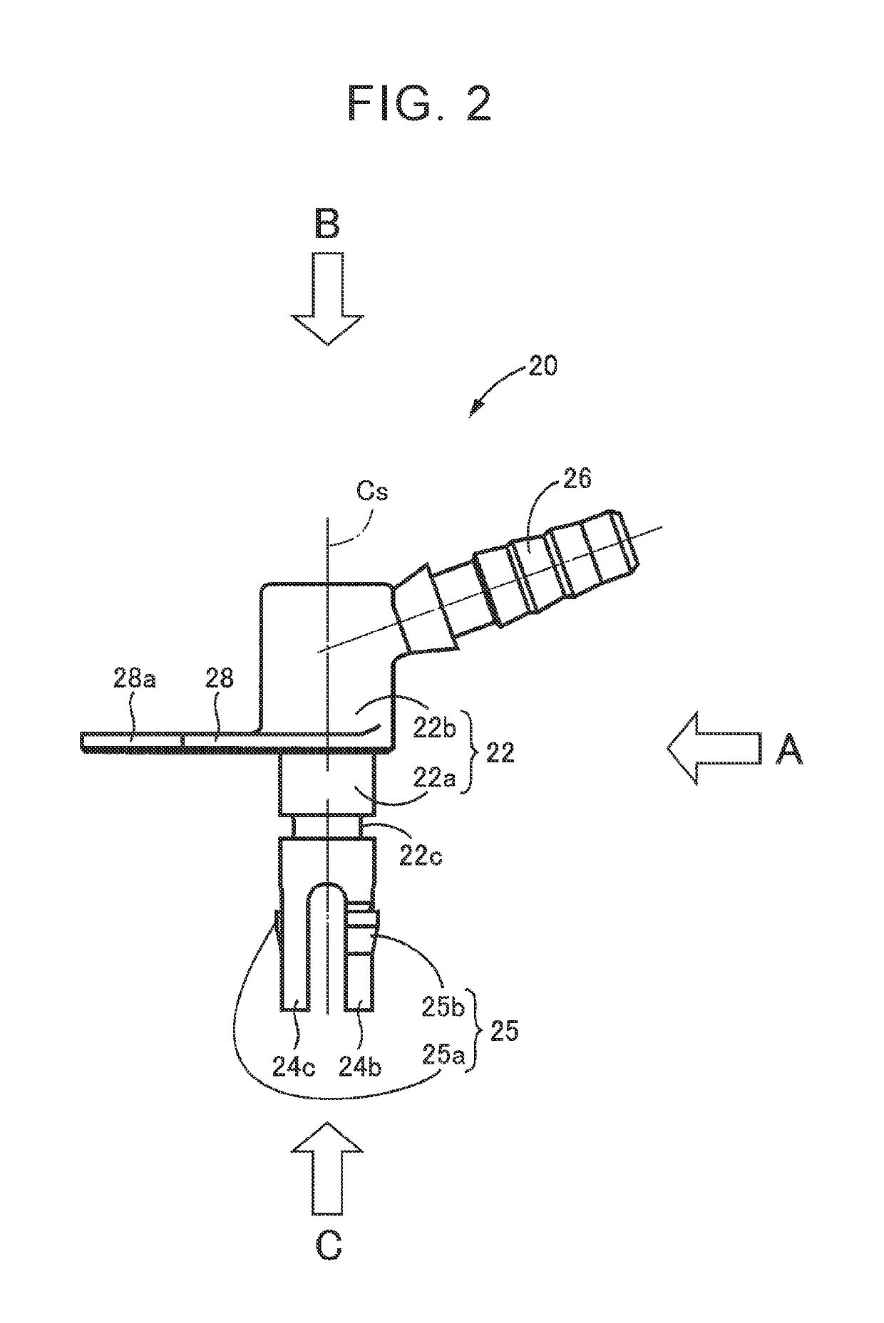
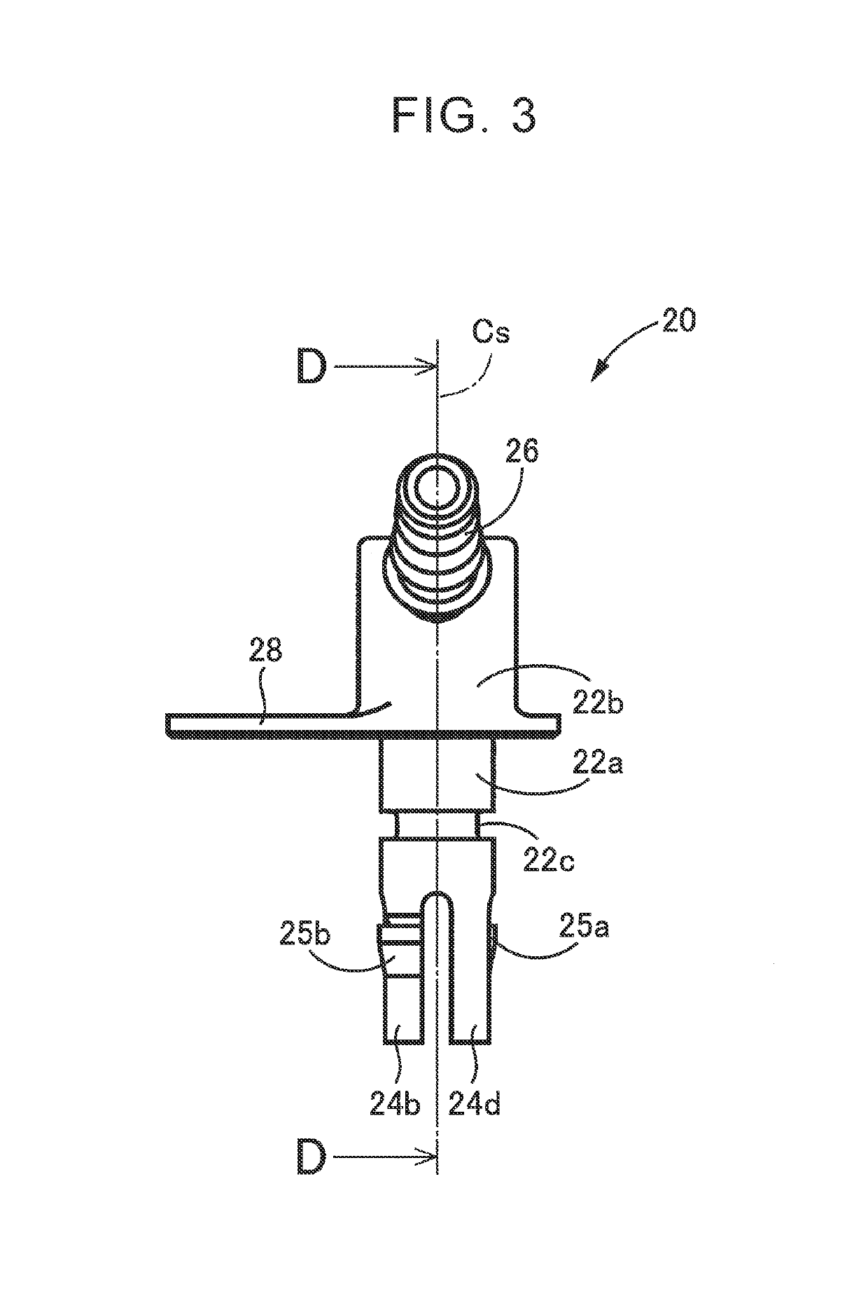
[0023]FIG. 1 is an outside drawing schematically illustrating a housing 10 to which a plug 20 for a vehicle (hereinafter just referred to as the plug 20) is attached (see a circled part indicated by an alternate long and short dash line in FIG. 1). The present disclosure is applied to the plug 20. FIG. 2 is an outside drawing schematically illustrating the plug 20. FIG. 3 is an outside drawing of the plug 20 illustrated in FIG. 2, when viewed from A. FIG. 4 is an outside drawing of the plug 20 illustrated in FIG. 2, when viewed from B. FIG. 5 is an outside drawing of the plug 20 illustrated in FIG. 2, when viewed from C. FIG. 6 is a sectional view taken along a line D-D in the outside drawing viewed from A in FIG. 3. FIG. 7 is a view illustrating a state where the plug 20 is attached to the housing 10, together with the outside drawing of FIG. 2, the outside drawing v...


PUM


Abstract

A plug for a vehicle includes: a body portion; a plurality of insertion portions configured to be inserted into a through-hole provided in a housing; and a flange portion having a notch formed on an outer periphery so as to restrict a rotation of the body portion around an axial center. The insertion portions are formed at two positions opposed to each other across a straight line passing through the notch and the axial center and are provided with retaining lugs engageable with the through-hole.

Description

INCORPORATION BY REFERENCE[0001]The disclosure of Japanese Patent Application No. 2016-188867 filed on Sep. 27, 2016 including the specification, drawings and abstract is incorporated herein by reference in its entirety.BACKGROUND1. Technical Field[0002]The present disclosure relates to a plug for a vehicle, the plug being inserted into a through-hole provided in a housing.2. Description of Related Art[0003]There has been well known a plug for a vehicle, including: a body portion having a circular-column outer shape and partially inserted into a through-hole provided in a housing; and a plurality of insertion portions formed integrally at intervals around an axial center of the body portion so as to extend from one end of the body portion in a direction parallel to the axial center, the plurality of insertion portions being inserted into the through-hole. An example thereof is a breather plug described in Japanese Patent Application Publication No. 2008-180313 (JP 2008-180313 A). JP...

Claims


Application Information

Patent Timeline
Patent Type & Authority Patents(United States)
IPC IPC(8): F16K24/04F16H57/031F16H57/035F16L41/08F16L41/12F16L37/00F16H57/027
CPCF16H57/027F16H57/031F16H57/035F16L41/12F16L37/008F16L41/086F16K24/04
Inventor MATSUMOTO, TAKUYAKONO, TETSUYA
Owner TOYOTA JIDOSHA KK
Why Eureka
Try Eureka