Optical input apparatus wherein light sources selectively emit light as the apparatus is inclined

a technology of input apparatus and light source, which is applied in the field of optical input apparatus, can solve the problem that the light emitted from one light source b>13/b> requires a high power consumption to realize a bright imag

Inactive Publication Date: 2016-03-08
SAMSUNG ELECTRONICS CO LTD
View PDF3 Cites 0 Cited by
  • Summary
  • Abstract
  • Description
  • Claims
  • Application Information

AI Technical Summary

Benefits of technology

[0011]The present invention has been made to address at least the problems and disadvantages described above, and to provide at least the advantages described below. Accordingly, aspects of the present invention provide an optical input apparatus that prevents generation of a locally saturated area of a pattern received by an image sensor according to a change of an external environment such as an inclination of the optical input apparatus.
[0012]Another aspect of the present invention provides an optical input apparatus that constantly maintains an image brightness as the optical input apparatus is inclined, prevents a local saturation, and allows a clear pattern to be detected by an image sensor.
[0013]Another aspect of the present invention provides an optical input apparatus that detects a brighter image even for a short exposure time, and reduces power consumption for an increase in the brightness of light of light sources.

Problems solved by technology

In addition, the light emitted from one light source 13 requires a high power consumption to realize a bright image with a short exposure time.

Method used


Image

  • Optical input apparatus wherein light sources selectively emit light as the apparatus is inclined
  • Optical input apparatus wherein light sources selectively emit light as the apparatus is inclined
  • Optical input apparatus wherein light sources selectively emit light as the apparatus is inclined

Examples


Embodiment Construction

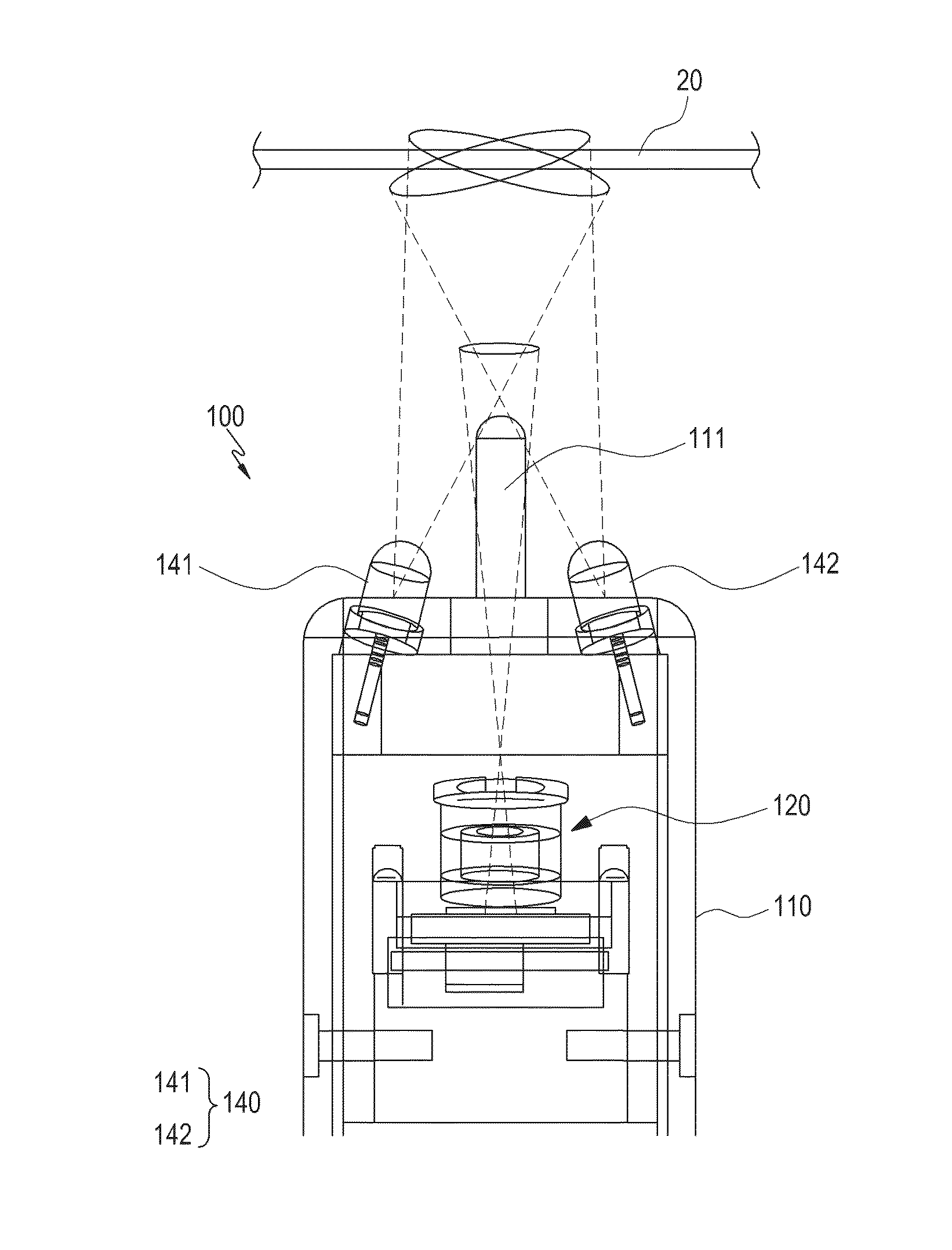
[0030]Hereinafter, embodiments of the present invention will be described with reference to the accompanying drawings. In the description, thicknesses of lines shown in the drawings and sizes of constituent elements may be exaggerated for clarity and convenience. Further, the following terms are defined considering their functions in the present disclosure and may be varied according to intentions and customs of a user or manager. Thus, the terms should be defined based on the contents of the entire disclosure. Further, although ordinal numbers such as first and second are used in the description of the embodiments of the present invention, their sequence may be arbitrarily determined and the description of the preceding elements may be applied to the description of the succeeding elements.

[0031]One aspect of an optical input apparatus according to an embodiment of the present invention is that a decrease in the brightness of a pattern detected by an image sensor can be prevented as...


PUM


Abstract

An optical input apparatus is provided. The optical input apparatus includes a body having an image sensor; a plurality of light sources provided in the body to emit light; and a controller configured to control emission of light by the plurality of light sources as a function of a pattern received by the image sensor, wherein the plurality of light sources selectively emit light according to a location of a local saturation of light received by the image sensor.

Description

PRIORITY[0001]This application claims priority under 35 U.S.C. §119(a) to Korean Application Serial No. 10-2012-0148925, which was filed in the Korean Intellectual Property Office on Dec. 18, 2012, the entire content of which is incorporated herein by reference.BACKGROUND OF THE INVENTION[0002]1. Field of the Invention[0003]The present disclosure generally relates to an optical input apparatus.[0004]2. Description of the Related Art[0005]Generally, portable electronic devices include portable terminals, MP3 players, Portable Multimedia Players (PMPs), and electronic books, and refer to devices by which users can access various contents while carrying the portable electronic devices.[0006]The portable electronic devices are frequently used while users are mobile due to their portability and various functions associated with the devices. The designs of the portable electronic devices are diversified according to the present day demands and the needs of consumers. Accordingly, portable...

Claims


Application Information

Patent Timeline
Patent Type & Authority Patents(United States)
IPC IPC(8): G06F3/03G06F3/0354G06F3/038
CPCG06F3/0308G06F3/0317G06F3/0386G06F3/03545G06F3/033G06F3/042H04N5/33
Inventor KIM, KANG-NAMYUN, IN-KUK
Owner SAMSUNG ELECTRONICS CO LTD
Why Eureka
Try Eureka