Noise suppression apparatus and control method thereof

a technology of noise suppression and noise suppression, applied in the field of noise suppression technique, can solve the problems of lowering the target sound suppression performance, unable to sufficiently suppress non-directional noise such as wind noise, and unable to accurately suppress etc., to achieve the effect of accurate suppression of only noise from the audio signal

Active Publication Date: 2016-03-08
CANON KK
View PDF7 Cites 23 Cited by
  • Summary
  • Abstract
  • Description
  • Claims
  • Application Information

AI Technical Summary

Benefits of technology

[0019]The present invention has been made to solve the aforementioned problems. That is, the present invention provides a noise suppression apparatus which can extract only non-directional noise from an audio signal without mixing any directional target sound, and can accurately suppress only noise from the audio signal.

Problems solved by technology

For this reason, even when a moderate main lobe of the beam pattern is used, non-directional noise such as wind noise cannot be sufficiently suppressed.
However, the adaptive beamformer suffers the following problems.
However, the method of Japanese Patent Laid-Open No. 2003-271191 suffers the following problems.
However, in non-directional noise extraction, since only a null to be directed to a directional target sound is originally required, if the direction of the main lobe is explicitly designated, it may influence the beam pattern, thus lowering a target sound suppression performance.
However, with this method, a null is formed in a direction of a perpendicular bisector of a line segment which connects microphones, and is not directed in the target sound direction.
However, as described above, the null of the fixed beamformer is not always directed to the target sound direction, and only an output power is checked.
Hence, this selection method is not always suitable to remove a target sound and to extract only noise.

Method used


Image

  • Noise suppression apparatus and control method thereof
  • Noise suppression apparatus and control method thereof
  • Noise suppression apparatus and control method thereof

Examples


first embodiment

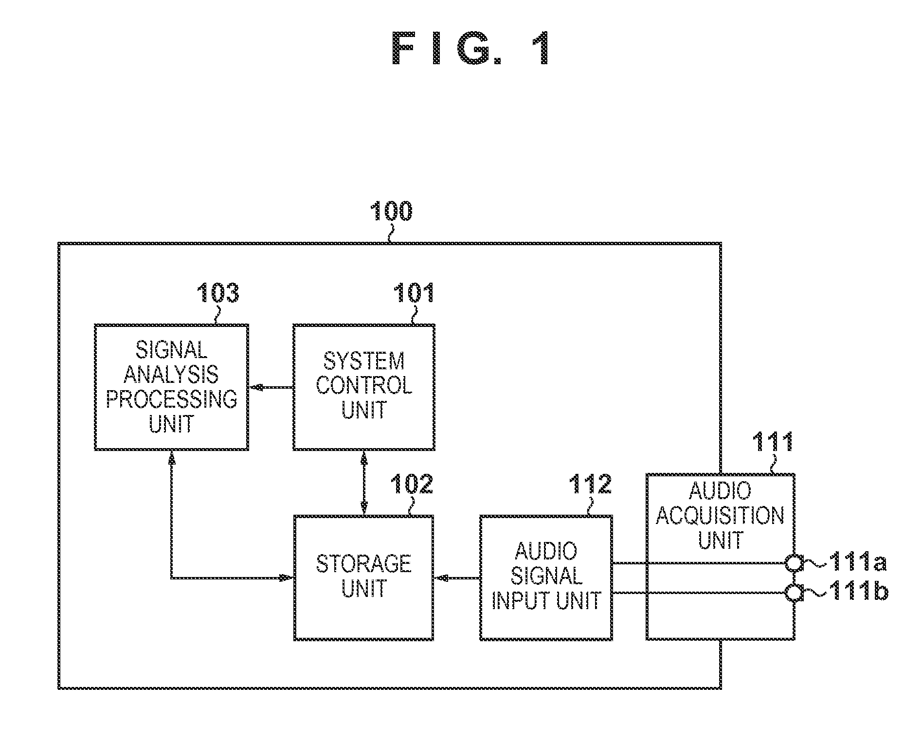
[0035]FIG. 1 is a block diagram showing an embodiment of the present invention. In a noise suppression apparatus shown in FIG. 1, a principal system controller 100 includes a system control unit 101 which controls all components, a storage unit 102 which stores various data, and a signal processing unit 103 which executes signal analysis processing.

[0036]The noise suppression apparatus includes an audio acquisition unit 111 and audio signal input unit 112 as components which implement functions of an audio acquisition system. In this embodiment, the audio acquisition unit 111 is configured by a 2ch stereo microphone including two microphone elements 111a and 111b which are disposed to be spaced apart from each other. Assume that the position coefficients of the respective microphone elements are held in advance in the storage unit 102. Alternatively, the position coefficients may be externally input via a data input / output unit (not shown) which is mutually connected to the storage ...

second embodiment

[0073]In the above embodiment, whether to select an adaptive beamformer or fixed beamformer is judged for each frequency. In the following embodiment, a switching frequency of beamformers is introduced in consideration of the tendency that the power of wind noise assumed as a practical example of non-directional noise becomes stronger as a frequency is lower.

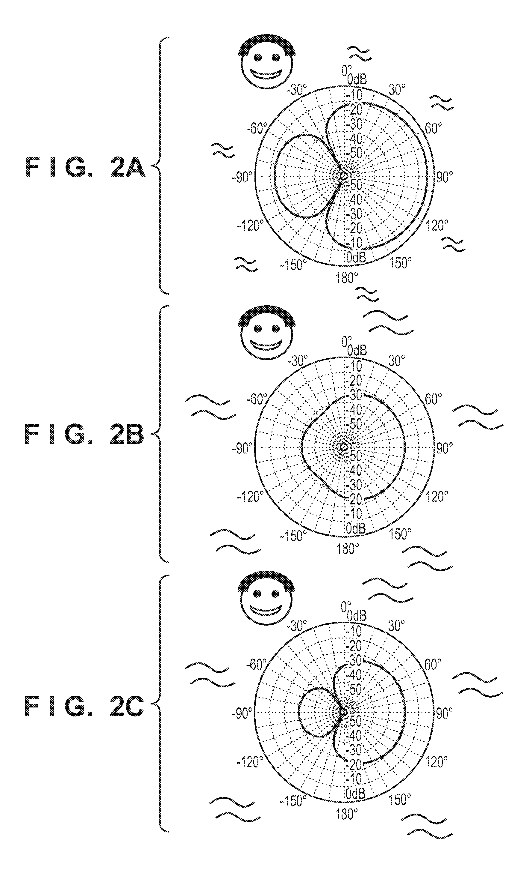
[0074]That is, in a frequency range not less than the switching frequency, the power of wind noise is smaller than a target sound, as shown in FIG. 2A, and it is considered that the adaptive beamformer automatically forms a sharp null in a target sound direction, thus selecting the adaptive beamformer. On the other hand, in a frequency range less than the switching frequency, it is considered that the power of wind noise is comparable to the target sound, and a moderate null is automatically formed by the adaptive beamformer, thus selecting the fixed beamformer, as shown in FIG. 2B.

[0075]As the switching frequency, for example, ...

third embodiment

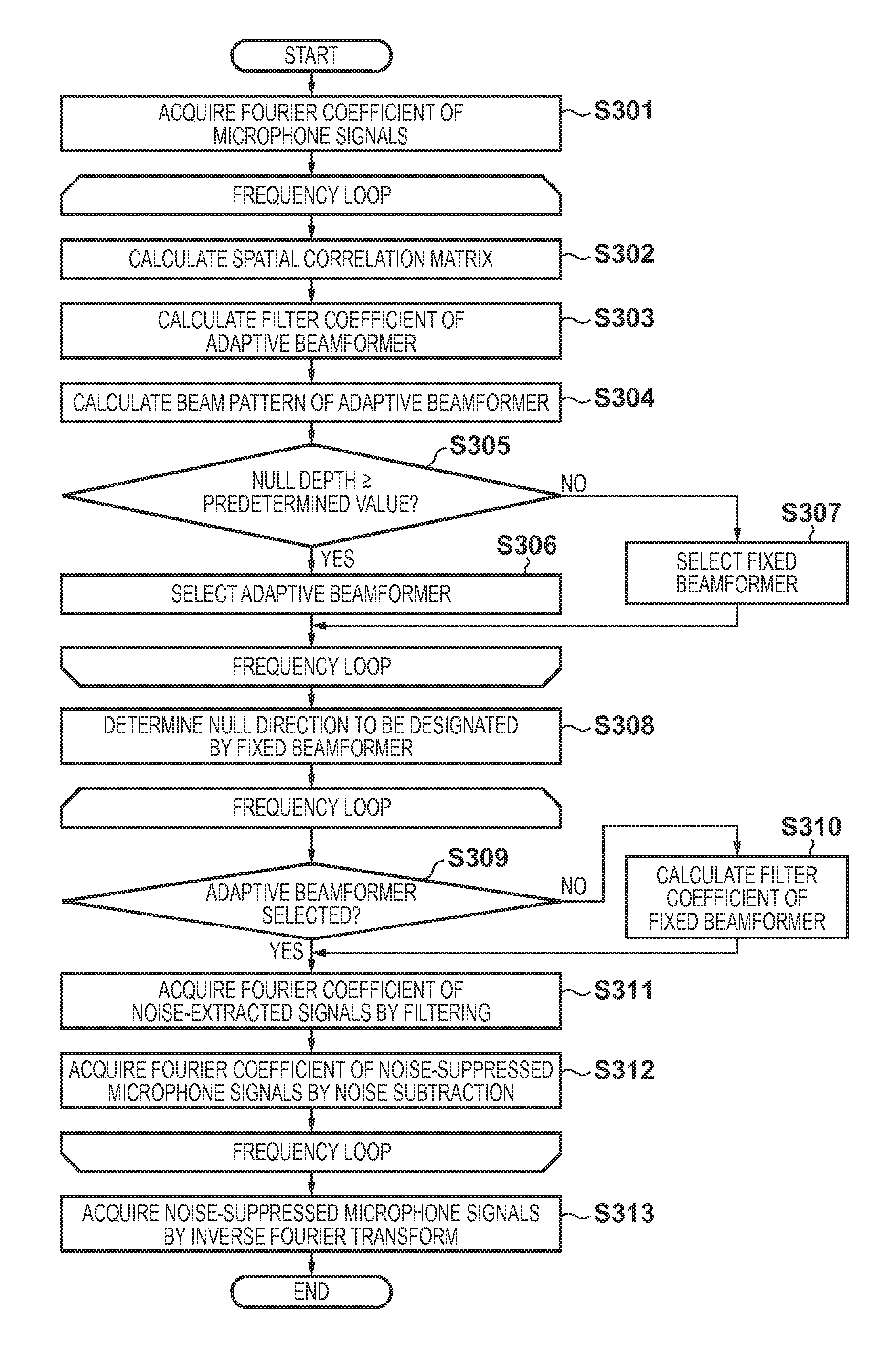
[0084]In this embodiment, a switching frequency is determined from noise extracted by an adaptive beamformer, and noise suppression processing is executed according to the flowchart shown in FIG. 7.

[0085]Since the process of step S701 is the same as that of step S301, a description thereof will not be repeated.

[0086]Steps S702 to S705 are processes for each frequency, and are executed in a frequency loop. The processes of steps S702 to S704 are the same as those of steps S302 to S304.

[0087]In step S705, by filtering microphone signals, as given by equation (8), Fourier coefficients Y(f) of noise-extracted signals are acquired. However, since filter coefficients of a beamformer calculated at this time are wadapt only, noise extraction is executed by the adaptive beamformer alone.

[0088]In step S706, a switching frequency is determined from the Fourier coefficients of the noise-extracted signals acquired in step S705.

[0089]FIG. 8 shows a spectrogram which displays amplitude spectra obt...


PUM


Abstract

A noise suppression apparatus selectively uses an adaptive beamformer and fixed beamformer for each frequency. A direction of a null of the fixed beamformer is determined from a direction of a null automatically formed by the adaptive beamformer. Filter coefficients of the adaptive beamformer based on an output power minimization rule are calculated by a minimum norm method using a norm of the filter coefficients as a constraint. The above selection is made based on, for example, a depth of a null automatically formed by the adaptive beamformer in the selection.

Description

BACKGROUND OF THE INVENTION[0001]1. Field of the Invention[0002]The present invention relates to a noise suppression technique for suppressing noise from an audio signal.[0003]2. Description of the Related Art[0004]A technique for suppressing unnecessary noise from an audio signal is important to enhance perceptual quality of a target sound included in an audio signal and to improve a recognition ratio in speech recognition.[0005]As a representative technique for suppressing noise from an audio signal, a beamformer is known. The beamformer applies filtering to each of a plurality of microphone signals acquired by a plurality of microphones, and then adds up the filtered signals to obtain a single output signal. This technique is called “beamformer” because the filtering and addition processes correspond to formation of a spatial beam pattern having directivity, that is, direction selectivity by the plurality of microphones.[0006]A portion where a gain of the beam pattern reaches a p...

Claims


Application Information

Patent Timeline
Patent Type & Authority Patents(United States)
IPC IPC(8): G10L21/0232G10L21/0216
CPCG10L21/0232G10L2021/02166
Inventor TAWADA, NORIAKI
Owner CANON KK
Why Eureka
Try Eureka