Seal-quality estimation for a seal for an ear canal

a seal quality and ear canal technology, applied in the field of determining the seal quality indication of an ear canal seal, can solve the problems of low computational complexity and low computational resources, and achieve the effects of low computational complexity, improved performance, and sufficiently reliable captur

Inactive Publication Date: 2016-03-08
KONINK PHILIPS ELECTRONICS NV
View PDF13 Cites 3 Cited by
  • Summary
  • Abstract
  • Description
  • Claims
  • Application Information

AI Technical Summary

Benefits of technology

[0010]The invention may provide an advantageous seal detection. The approach may for example allow body sound capturing applications to provide improved performance by ensuring that the seal is sufficient for sufficiently reliable capture. The approach may be of low computational complexity and may require only a low computational resource. For example, in a digital implementation a very low sample rate can be used to determine the seal quality. Indeed, in some embodiments a sample rate as low as 100 Hz may be used. Reliable estimates of the quality of the seal can be generated, and the seal quality indication may e.g. allow the reliability of body sound measurements to be estimated.
[0050]This may allow improved performance of applications based on capturing body sounds and may in particular allow improved reliability. For example, for reducing seal quality an increased low pass filtering of the microphone signal may be applied. As another example reduced weight may be applied to body sound measurements associated with an indication of a low seal quality compared to body sound measurements associated with an indication of a high seal quality.

Problems solved by technology

The approach may be of low computational complexity and may require only a low computational resource.

Method used


Image

  • Seal-quality estimation for a seal for an ear canal
  • Seal-quality estimation for a seal for an ear canal
  • Seal-quality estimation for a seal for an ear canal

Examples


Embodiment Construction

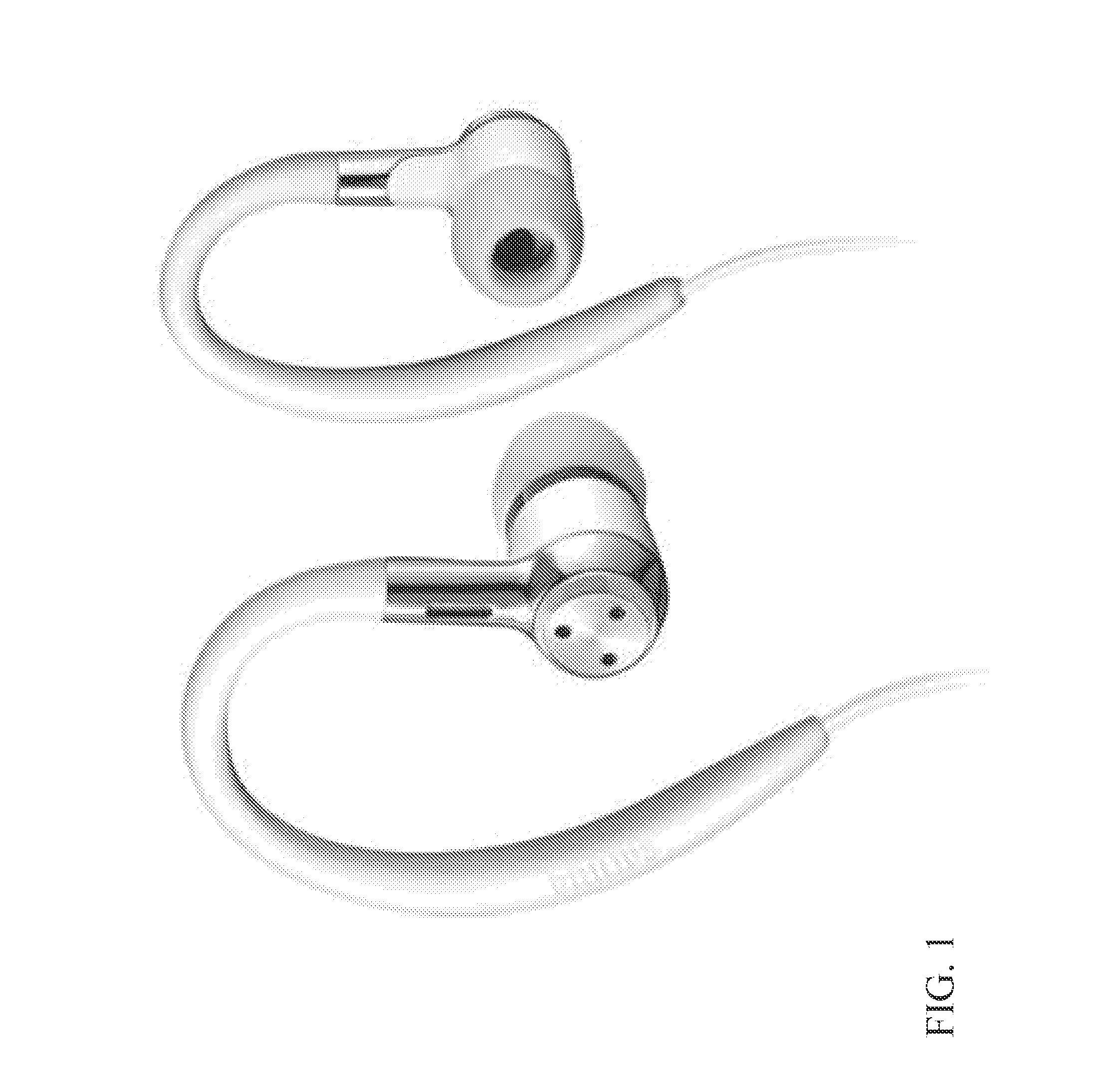
[0058]The following description focuses on embodiments of the invention applicable to determination of a seal quality for a sealed ear canal microphone and in particular to such seal detection for use in an application for measuring body sounds in the ear canal. However, it will be appreciated that the invention is not limited to this application but may be applied to any application using an in ear canal microphone together with a seal of the ear canal. It will also be appreciated that the approach may be used for any potential sealing of the ear canal and does not require this sealing to be made by the microphone element itself.

[0059]The approach will be described with reference to the seal of one ear but it will be appreciated that the approach can be applied in parallel to both ears. Indeed, in some cases a single seal quality indication for both ears can be generated by combining individual seal quality indications for both ears.

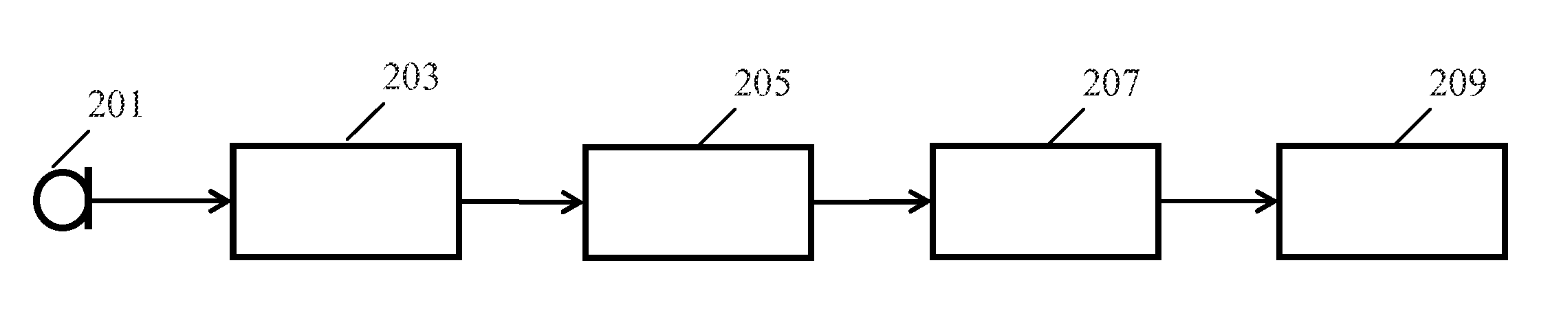
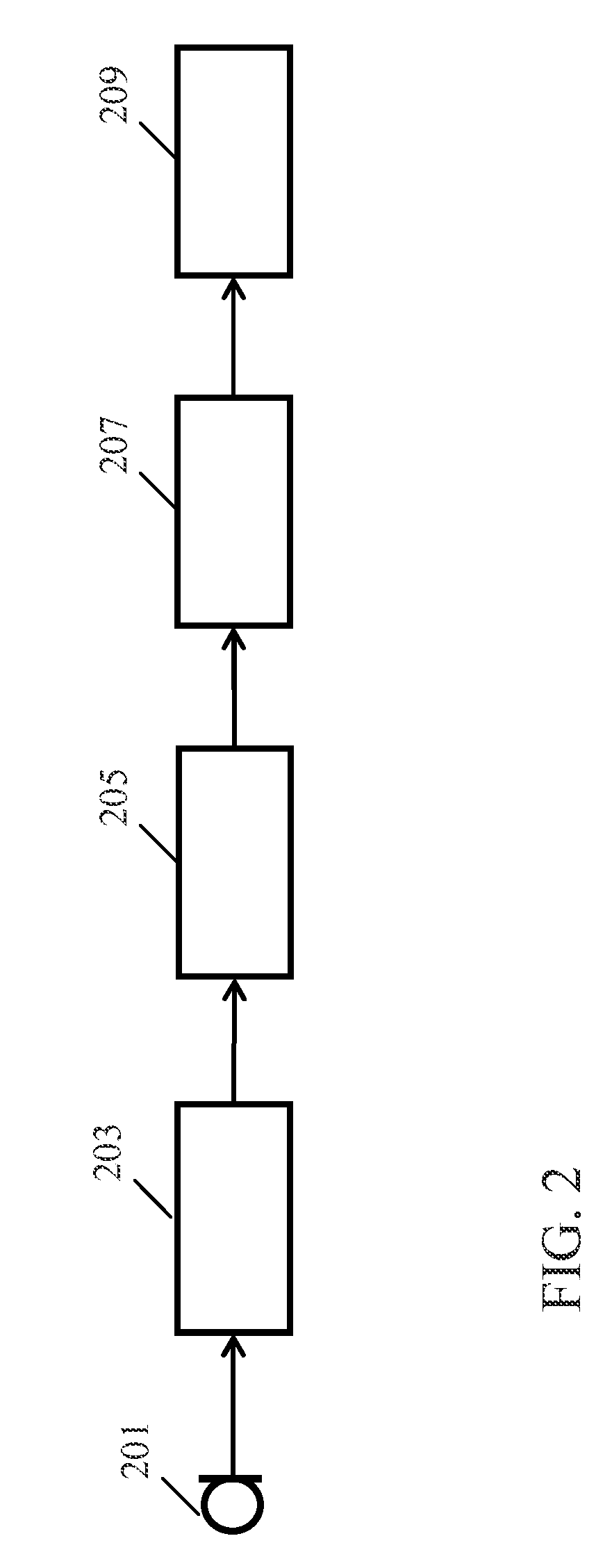
[0060]FIG. 2 illustrates an example of an apparat...


PUM


Abstract

Measurements of body sounds in the ear canal may be used for many applications. However, reliability is dependent on the ear canal being properly sealed to allow the body sounds to achieve a detectable level. An apparatus is therefore provided for determining a seal quality indication for a seal of an ear canal. An ear canal microphone (201) provides a microphone signal to an input (203) which is coupled to a circuit (205) for generating a first signal from the microphone signal. The first signal may be the same as the microphone signal. A circuit (209) then determines the seal quality in response to the frequency spectrum for the first signal. A frequency transformer (207) may perform a frequency transformation on the first signal to generate a frequency spectrum for the first signal and. The seal quality indication may specifically be generated based on a detection of a low frequency boost.

Description

FIELD OF THE INVENTION[0001]The invention relates to a method and apparatus for determining a seal quality indication for a seal of an ear canal and in particular, but not exclusively, to determination of a seal quality indication for body sound measuring applications.BACKGROUND OF THE INVENTION[0002]There is an increasing interest in monitoring body functions for various applications. For example, there is an interest in monitoring heart rate and breathing characteristics for relaxation, exercise and medical applications.[0003]It has been proposed to measure body sounds by placing a microphone in the ear canal. Indeed body sounds, are transmitted through the body via bone conduction, among others. Interesting sounds that can be captured inside the ear canal include heart sounds, breathing sounds and motion sounds such as footsteps. It has been found that it is possible to record such body sounds inside the ear canal by making use of what is known as the occlusion effect. The occlus...

Claims


Application Information

Patent Timeline
Patent Type & Authority Patents(United States)
IPC IPC(8): H04R29/00H04R25/00
CPCH04R29/00H04R25/30H04R2430/03H04R2460/15
Inventor DUISTERS, RONALD, PETRUS, NICOLAAS
Owner KONINK PHILIPS ELECTRONICS NV
Why Eureka
Try Eureka