Demodulation Method and Receiving Device

a demodulation method and receiving device technology, applied in digital transmission, spatial transmit diversity, diversity/multi-antenna system, etc., can solve problems such as too large computation complexity, and achieve the effect of low computation complexity

Inactive Publication Date: 2018-08-16
REALTEK SEMICON CORP
View PDF3 Cites 3 Cited by
  • Summary
  • Abstract
  • Description
  • Claims
  • Application Information

AI Technical Summary

Benefits of technology

[0004]It is therefore a primary objective of the present disclosure to provide a demodulation method and a receiving device with low computation complexity, to improve over disadvantages of the prior art.

Problems solved by technology

However, under a condition that the spatial data is transmitted toward multiple users, one user would not know about the existence of other users.
Nevertheless, to exhaustively search all possibility of multiple users, the MLD operation requires lots of dividers, such that the computation complexity is too large.

Method used


Image

  • Demodulation Method and Receiving Device
  • Demodulation Method and Receiving Device
  • Demodulation Method and Receiving Device

Examples


Embodiment Construction

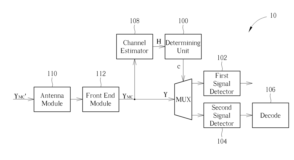
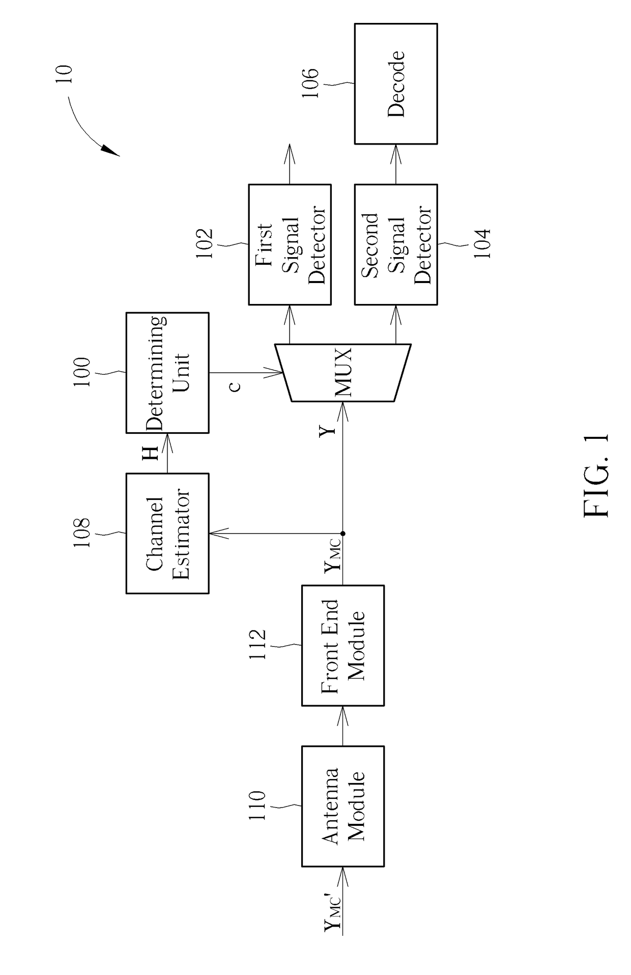
[0010]FIG. 1 is a schematic diagram of a receiving device 10 according to an embodiment of the present disclosure. The receiving device 10 maybe a UE (User Equipment) within an LTE (Long-Term Evolution) system or a wireless station within a WLAN (Wireless Local-Area Network), and is a receiving end within a wireless communication system. The receiving device 10 receives a signal S generated by a transmitting device (not illustrated in FIG. 1), where the transmitting device maybe an eNB (Evolved Node B) within the LTE system or another wireless station within the WLAN system. The transmitting device may comprise a plurality of antennas, and the signal S may be a signal generated by OFDM (Orthogonal Frequency Division Multiplexing) and / or beamforming technology.

[0011]The signal S transmitted by the transmitting device may comprise a plurality of layers (multi-layers) of spatial data, which is transmitted toward the receiving device 10 and other subscribers other than the receiving dev...


PUM


Abstract

The present disclosure provides a demodulation method. The demodulation method includes obtaining a received signal; determining whether a multiuser interference is smaller than a threshold; performing a first signal detection operation on the received signal if the multiuser interference is smaller than the threshold, in which the first signal detection operation detects a single layer of spatial data in the received signal; and performing a second signal detection operation on the received signal if the multiuser interference is greater than the threshold, in which the second signal detection operation detects multiple layers of spatial data in the received signal.

Description

BACKGROUND OF THE INVENTION1. Field of the Invention[0001]The present disclosure relates to a demodulation method and a receiving device, and more particularly, to a demodulation method and a receiving device with low computation complexity.2. Description of the Prior Art[0002]In wireless communication systems, user's demand of high data rate transmission is increasing. Beamforming technology under MIMO (multiple-input-multiple-output) technology may enhance data rate without increasing bandwidth and is attracting more attention. Beamforming technology, combining antenna and DSP (digital signal process) techniques, is able to enhance signal strength in a specific direction and suppress interference from others. Beamforming technology is also able to transmit multiple layers of spatial data, where the multiple layers of spatial data may be only transmitted to a single user or transmitted toward multiple users. However, under a condition that the spatial data is transmitted toward mul...

Claims


Application Information

Patent Timeline
Patent Type & Authority Applications(United States)
IPC IPC(8): H04B7/08H04L27/233
CPCH04B7/0857H04L1/0054H04L27/2331H04L1/0045
Inventor CHANG, CHUNG-YAOHUANG, WEI-CHIEHYANG, YI-SYUN
Owner REALTEK SEMICON CORP
Why Eureka
Try Eureka