
Golf cage system

Inactive Publication Date: 2016-03-22
ALLEN DILLIS V
View PDF18 Cites 9 Cited by
  • Summary
  • Abstract
  • Description
  • Claims
  • Application Information

AI Technical Summary

Benefits of technology

The present invention provides a golf cage system that uses the customer's garage door tracks as the frame for the cage. This helps to minimize track twisting by transferring loads from ball impact in a perpendicular direction. The cage has a ball striking drop panel suspended from a shaft mounted on rollers or end caps that ride in the rails and fastened to the tracks in their active position. Additionally, side panels and a top panel are supported on the rollers at their forward ends and supported on another set of rollers in the tracks at the distal ends of the tracks. The cage is low-profile and designed to be unobstructed for foot and tire traffic.

Problems solved by technology

Because these cages are designed for outdoor use, they frequently create an errant ball hazard when erected and used in the garage.

Method used


Image

  • Golf cage system
  • Golf cage system
  • Golf cage system

Examples


Embodiment Construction

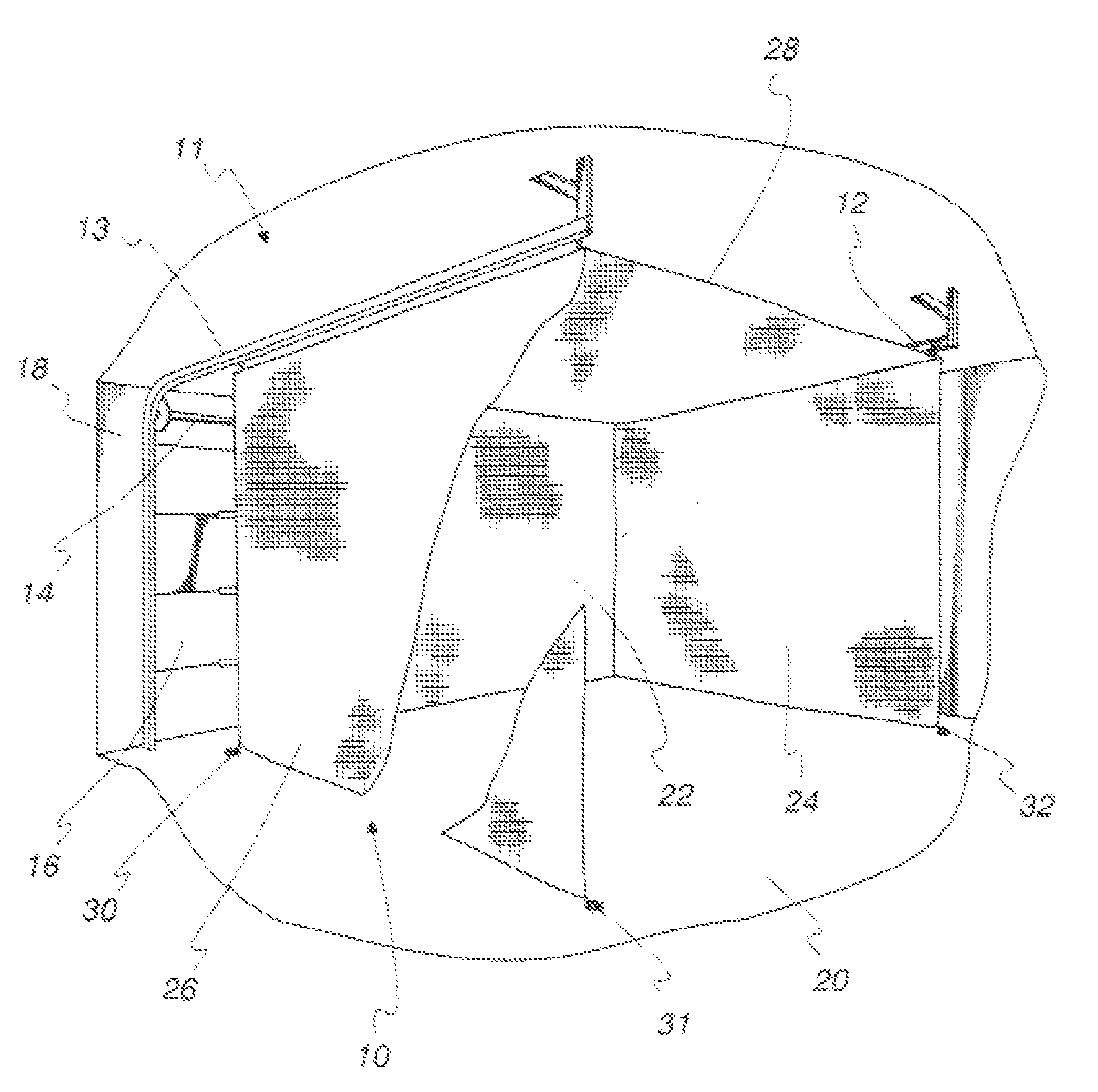
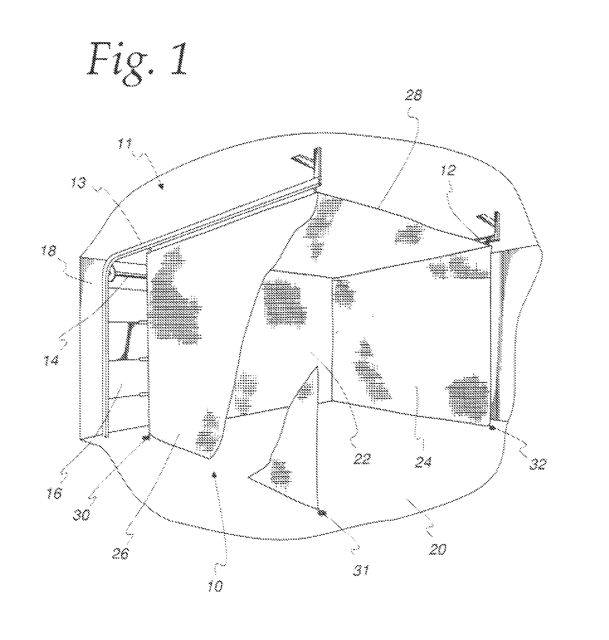
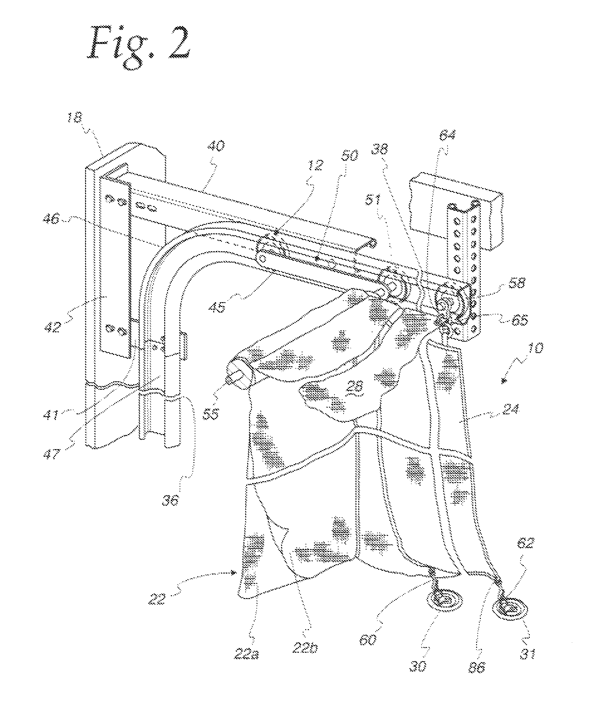
[0018]Referring to the drawings and initially to the perspective of FIG. 1, a golf or sports cage system is generally designated by the reference numeral 10 and is seen to be supported in a standard garage door opening and dosing system 11 including a left track 12, a right track 13, a torsion spring assembly 14 permitting a segmented door assembly 16 to open and close from its closed position illustrated in FIG. 1. The tracks 12 and 13 are supported by brackets shown in FIGS. 2 and 5 on a door frame 18. The tie-downs for the golf cage system 10 are permanently affixed to the concrete garage floor 20, as will be seen from the following views.

[0019]The golf cage system 10 is supported on the horizontal portion of the side tracks 12 and 13 and is seen to include a forward ball striking double panel 22, a left side panel 24, a right side panel 26, and a top panel 28.

[0020]It should he understood that the panels 22, 24, 26 and 28 can be constructed of a netting material common in the go...


PUM


Abstract

A golf cage system that uses the customer's garage door tracks as the frame for the cage. The cage is oriented to transfer loads from ball impact through the tracks to the frame of the door in a perpendicular direction to minimize track twisting. The cage has a ball striking drop panel suspended from a shaft mounted on rollers or end caps that ride in the tracks and fastened to the tracks in their active position. Side panels and a top panel are also supported on the rollers at their forward ends and supported on another set of rollers in the tracks at the distal ends of the tracks. Low profile tie-downs are epoxied to the concrete garage floor to facilitate unobstructed foot and tire traffic.

Description

BACKGROUND OF THE INVENTION[0001]Golf cages require framing as well as netting and the frames contribute in many cases more than 50% of the cost of manufacturing the cage.[0002]Golf cage systems in the garage have been increasingly popular because they enable the golfer to practice during inclement weather. Because these cages are designed for outdoor use, they frequently create an errant ball hazard when erected and used in the garage.[0003]It is a primary object of the present invention to ameliorate these problems in garage located golf cages and provide a lower cost golf cage system for the garage.SUMMARY OF THE PRESENT INVENTION[0004]In accordance with the present invention, a golf cage system is provided that uses the customer's garage door tracks as the frame for the cage. The cage is oriented to transfer loads from ball impact through the tracks into the frame of the door in a perpendicular direction to minimize track twisting. The cage has a ball striking drop panel suspend...

Claims


Application Information

Patent Timeline
IPC IPC(8): A63B69/36A63B71/02A63B63/00
CPCA63B71/022A63B69/36A63B63/00A63B2063/006A63B2071/024A63B2210/50A63B2225/09
Inventor ALLEN, DILLIS, V.
Owner ALLEN DILLIS V
Learn More