Filter frame header locking device

a locking device and filter frame technology, applied in the field of pocket filter assemblies, can solve the problems of large air stream pressure loss, large and bulky filters, and attendant increase in energy required to operate the system, so as to minimize overall racking and twisting, and reduce the effect of racking and twisting

Active Publication Date: 2018-08-09
WEISBACH JOHN F
View PDF0 Cites 7 Cited by
  • Summary
  • Abstract
  • Description
  • Claims
  • Application Information

AI Technical Summary

Benefits of technology

[0022]It is an object of the present invention to provide a means for adjusting a header frame in order for it to be pushed together tightly and remove any “rattle” in the joint or connection and minimize overall racking and twisting in the frame increasing rigidity.
[0023]It is an object of this invention to provide multi-bag filter cartridge including a main rectangular frame holding the wedge-shaped bags together in a side-by side arrangement wherein the channel includes two shoulders spaced apart from the inner-most surface of the channel, thus providing a more rigid frame and a particular spacing of the filter bags within the frame.

Problems solved by technology

If this is not done, there can be a substantial pressure loss in the air stream as it flows through the filter cartridge with an attendant increase in the energy required to operate the system.
However, while that type of arrangement has proven to be very effective in maintaining separation between the adjacent filter bags, the filter media proximate each of the seams is unavailable for filtering and thus larger and bulkier filters have generally been required.
This approach has also proven effective but similarly has required the use of larger filters as well as being relatively difficult to manufacture.
However, while that type of arrangement is very effective in maintaining separation between the adjacent filter bags, the filter media around each of the seams is unavailable for filtering thus reducing filter efficiency.
This approach has also proven effective but similarly requires the use of larger filters which are relatively difficult to manufacture.

Method used


Image

  • Filter frame header locking device
  • Filter frame header locking device
  • Filter frame header locking device

Examples


Embodiment Construction

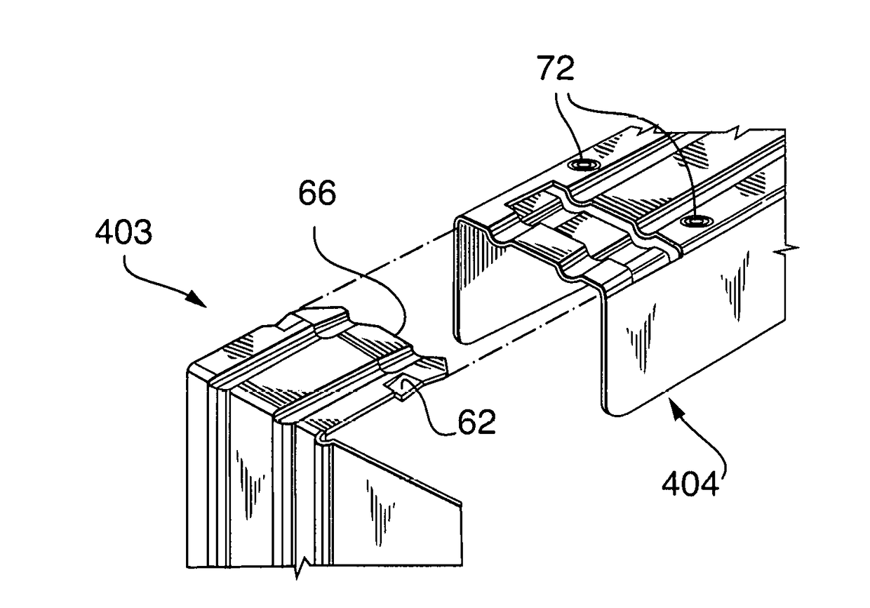
[0058]Pocket filter assemblies having at least one and typically a plurality of filter bags having an open end attaching to a rectangular flat sub-frame fastened inside the open end of the bag. The sub-frames are fastened together, side by side, and then the sub-frame and bag assembly is supported by a filter frame header wherein the sub-frame is inserted into an inward facing U-shaped channel of a corresponding sized and shaped main header frame. The header frame is made from a longitudinal channel having miters spaced out along the channel and a distal end. The inner miters are bent at right angles with the U-channel facing inward. The filter frame header locking device holds the ends of the header frame together after installation of the sub-frames.

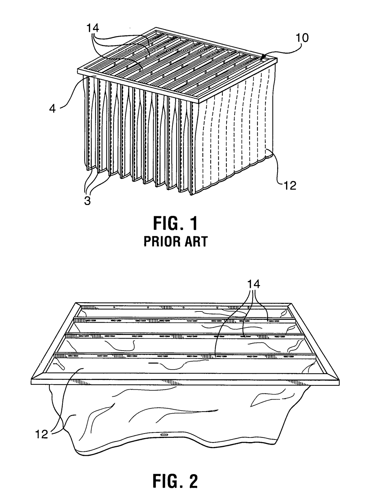
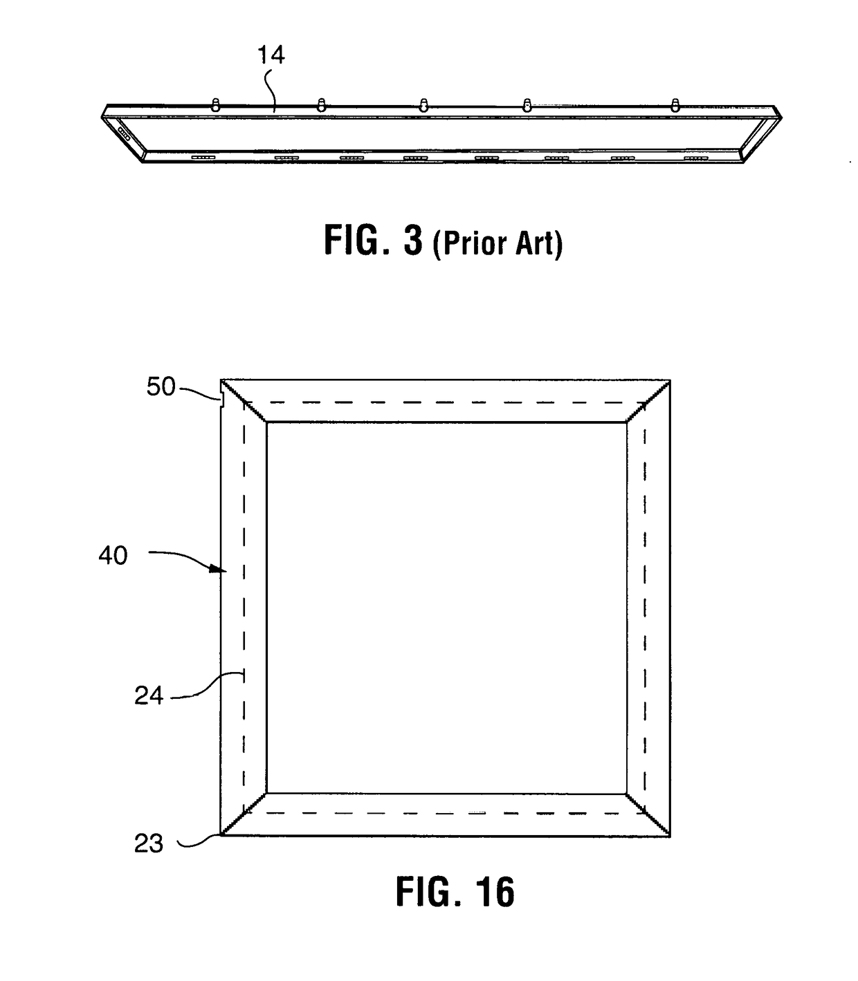
[0059]In accordance with the drawings, there is provided a filter cartridge 10, containing a plurality of filter bags 12 having a sub-frame 14 inserted in the open ends thereof and fastened to one another is side-by-side arrangement, t...


PUM

PropertyMeasurementUnit
angleaaaaaaaaaa
90 degree anglesaaaaaaaaaa
angleaaaaaaaaaa

Abstract

A header containing a multi-toothed tab forming a series of ratchets formed therein cooperatively engages a lanced section extending across the web of the cross section and depressed toward the inside of the cross section a selected depth that is greater than the tab thickness. One edge of the lanced and formed surface is formed with an upturned lip that functions as a pawl for the ratchets on the tab. Insertion of the tab into the lanced section of the receiver, each ratchet will be forced over the paw of the lanced section. The lanced section acts as a spring to allow the ratchet to pass over the paw and then pop back to its previous location ready to be flexed again for the next ratchet.
The header includes a longitudinal channel having a base channel and upwardly extending channel sidewalls and a pair of spaced apart aligned longitudinal reinforcement ribs extending along said longitudinal channel base. The channel sidewalls including a pair of inwardly projecting longitudinal shoulders spaced apart from and aligned with the reinforcement ribs. The longitudinal channel member include a first male end including a tab with two lateral half tangs for cooperatively engaging an opposing channel receiver including two lateral lanced portions forming inwardly raised transverse flanges on either side of said channel base, each with an upwardly projecting lip for cooperative engagement with the two tangs disposed on the tab surface of the opposing distal end of the longitudinal channel member. The channel receiver has two inwardly extending dimples which cooperatively engage an inwardly canted end portion of the tab to maintain engagement of the tangs with said upwardly projecting lips.

Description

TECHNICAL FIELD[0001]The present invention relates to the field of pocket filter assemblies for supporting filter media bags for removing solids from air or gaseous mediums wherein the filter whereby multiple bag filter elements held together in a sub-frame are supported by a rectangular header frame.BACKGROUND OF THE INVENTION[0002]Typically, a filter cartridge is fixed across the interior of a gas duct so that particulate materials are removed from the gas stream flowing through the interior of each of the filter pockets. When it becomes necessary to replace the filter media in the filter cartridge, the entire cartridge is removed and thrown away and a new cartridge installed in its place.[0003]A common type of air filter referred to as a pocket filter cartridge generally includes a plurality of relatively flat wedge-shaped filter bags fastened to a common mounting frame so that the cartridge includes a series of filter pockets suspended from the frame in adjacent side-by-side rel...

Claims


Application Information

Patent Timeline
Patent Type & Authority Applications(United States)
IPC IPC(8): B01D46/00B01D46/02
CPCB01D46/0005B01D46/023B01D46/0016
Inventor WEISBACH, JOHN F.
Owner WEISBACH JOHN F
Why Eureka
Try Eureka