Synchronized patient elevation and positioning apparatus for use with patient positioning support systems
What is AI technical title?
AI technical title is built by Patsnap AI team. It summarizes the technical point description of the patent document.
a positioning support system and positioning apparatus technology, applied in the field of patient positioning apparatus, can solve the problems of difficult positioning procedures and compromise of surgical si
Active Publication Date: 2016-03-29
WARSAW ORTHOPEDIC INC
View PDF193 Cites 47 Cited by
Summary
Abstract
Description
Claims
Application Information
AI Technical Summary
This helps you quickly interpret patents by identifying the three key elements:
Problems solved by technology
Method used
Benefits of technology
Problems solved by technology
Such transfer procedures interrupt the surgical procedure, are cumbersome, and may compromise the surgical site.
Since the patient starts in a supine position on a gurney, also referred to as a trolley or a stretcher, and must be transferred to a prone position on an open frame support, such positioning procedures can be quite difficult.
Method used
Image
Click on the blue label to locate the original text in one second.
Reading with bidirectional positioning of images and text.
Examples
Embodiment Construction
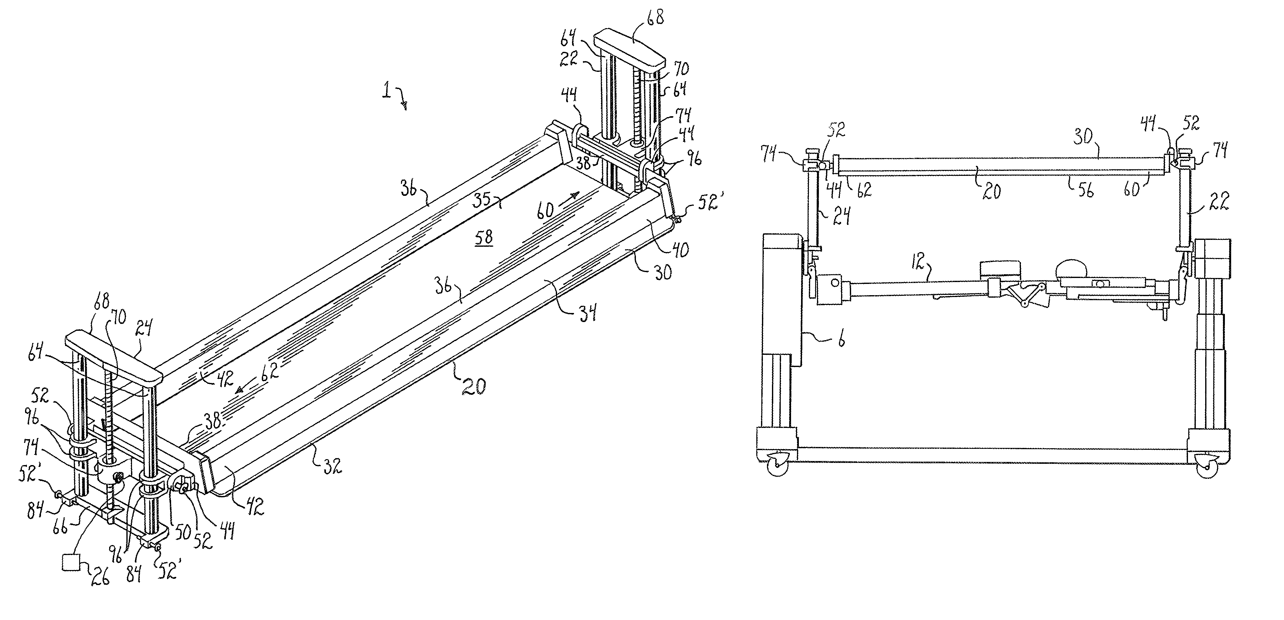
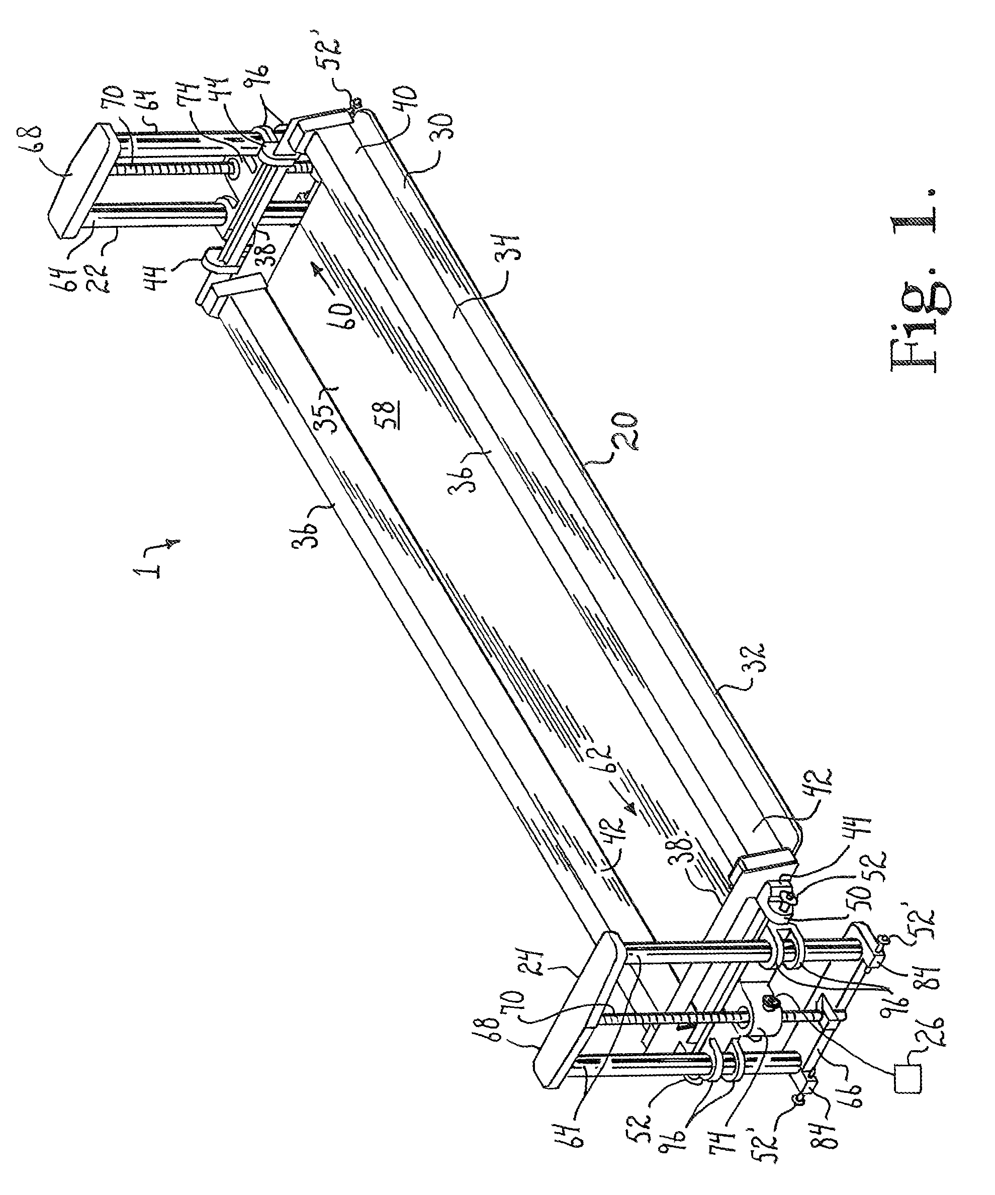
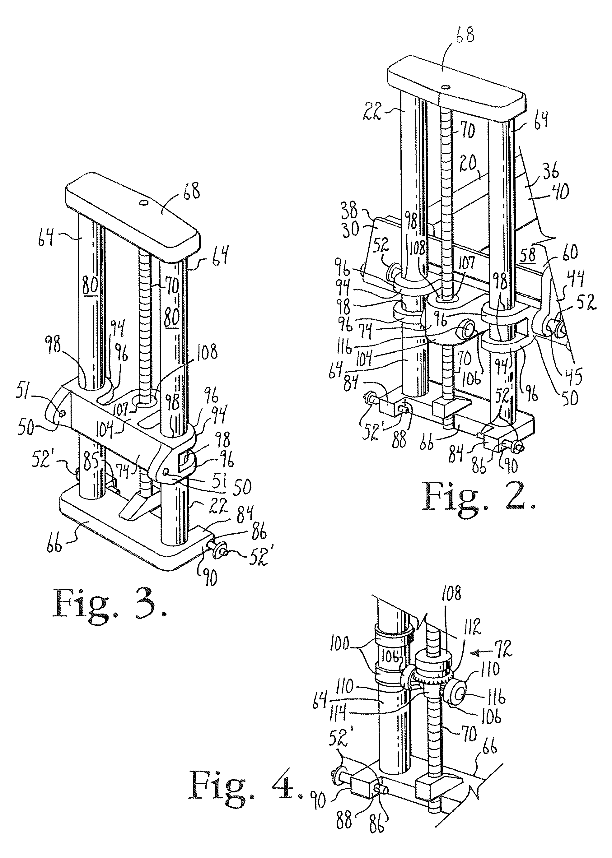
[0051]As required, detailed embodiments of the present invention are disclosed herein; however, it is to be understood that the disclosed embodiments are merely exemplary of the invention, which may be embodied in various forms. Therefore, specific structural and functional details disclosed herein are not to be interpreted as limiting, but merely as a basis for the claims and as a representative basis for teaching one skilled in the art to variously employ the present invention in virtually any appropriately detailed structure.
[0052]Referring now to the drawings, a patient positioning apparatus of the present invention is generally denoted by the numeral 1. The patient positioning apparatus is useful for positioning a patient 2 in a prone position on a patient support structure 4, or surgical table, such as for a medical procedure. An exemplary patient support structure 4 is shown in FIGS. 8-13.
[0053]Numerous patient support structures 4 find use with the patient positioning appara...
PUM
Abstract
An apparatus for transferring a supine patient to a prone position on a patient support structure, and for rotating such a prone patient between prone and supine positions without removing the patient from the patient support structure.
Description
CROSS-REFERENCE TO RELATED APPLICATIONS[0001]This application claims the benefit of U.S. Provisional Application No. 61 / 742,167 filed Aug. 3, 2012 and entitled “Synchronized Patient Elevation And Positioning Apparatus For Use With Patient Positioning Support Systems,” the entirety of which is incorporated by reference herein.[0002]This application is also a Continuation-In-Part of U.S. patent application Ser. No. 13 / 317,012, now U.S. Pat. No. 8,719,979, which is a Continuation of U.S. patent application Ser. No. 12 / 460,702, now U.S. Pat. No. 8,060,960, and also which is a Continuation of U.S. patent application Ser. No. 11 / 788,513, now U.S. Pat. No. 7,565,708, each of which is incorporated by reference herein in its entirety.[0003]U.S. patent application Ser. No. 11 / 788,513 claims the benefit of U.S. Provisional Application No. 60 / 798,288, and is also a Continuation-In-Part of U.S. patent application Ser. No. 11 / 159,494, now U.S. Pat. No. 7,343,635, which is a Continuation-In-Part o...
Claims
Application Information
Patent Timeline
Application Date:The date an application was filed.
Publication Date:The date a patent or application was officially published.
First Publication Date:The earliest publication date of a patent with the same application number.
Issue Date:Publication date of the patent grant document.
PCT Entry Date:The Entry date of PCT National Phase.
Estimated Expiry Date:The statutory expiry date of a patent right according to the Patent Law, and it is the longest term of protection that the patent right can achieve without the termination of the patent right due to other reasons(Term extension factor has been taken into account ).
Invalid Date:Actual expiry date is based on effective date or publication date of legal transaction data of invalid patent.

