Apparatus for closed-loop mechanical energy harvesting

a closed-loop, mechanical energy harvesting technology, applied in the direction of electric apparatus, machines/engines, generators/motors, etc., can solve the problems of limited service time, impeding the advance of many electronics fields, and low energy density of electric devices, so as to achieve compact energy harvesting arrangements and create additional energy

Inactive Publication Date: 2016-04-12
KRUPENKIN THOMAS NIKITA +1
View PDF25 Cites 0 Cited by
  • Summary
  • Abstract
  • Description
  • Claims
  • Application Information

AI Technical Summary

Benefits of technology

[0013]Advantageously, the configuration of the present invention is able to sustain a smooth, continuous motion of the chain within the closed-loop channel by inertia for a period of time after the hydraulic actuation of the chain stops. This additional motion thus creates additional energy even in the absence of the hydraulic motion.
[0015]All of these advantages are thus considered to extend the power generation time, leading to an improvement in energy harvesting efficiency.

Problems solved by technology

Although battery quality has substantially improved over the last two decades, their energy density has not greatly increased.
At the present time, issues such as cost, weight, limited service time and waste disposal (all intrinsic to batteries) are impeding the advance of many areas of electronics.
The problem is especially acute in the area of portable electronic devices, where rapidly growing performance and sophistication of mobile electronic devices leads to ever-increasing power demands that electrochemical batteries are unable to meet.
High power harvesting of mechanical energy is a long-recognized concept that has not been commercialized in the past due to the lack of a viable energy harvesting technology.
Traditional methods of mechanical-to-electrical energy conversion such as electromagnetic, piezoelectric or electrostatic do not allow for effective “direct coupling” to the majority of high-power environmental mechanical energy sources.
Bulky and / or expensive mechanical or hydraulic transducers are often required to convert a broad range of aperiodic forces and displacements typically encountered in nature into a force accessible for conversion using those methods.

Method used


Image

  • Apparatus for closed-loop mechanical energy harvesting
  • Apparatus for closed-loop mechanical energy harvesting
  • Apparatus for closed-loop mechanical energy harvesting

Examples


Embodiment Construction

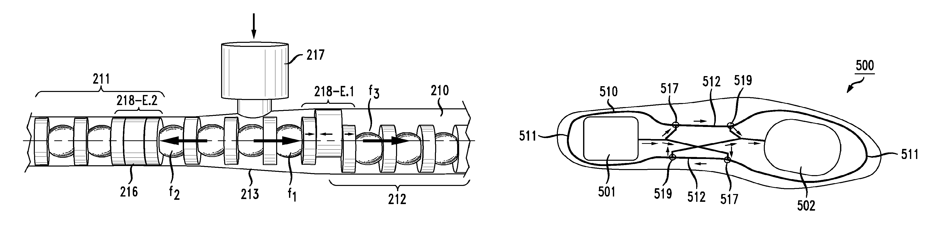
[0043]As will be described in detail below, the present invention addresses various problems of previous microfluidic-based energy harvesting arrangements, disclosing a new closed-loop energy harvesting apparatus that utilizes hydraulic actuation and allows for continuous, revolving motion of a chain of energy-producing elements within an energy-producing channel. A significant aspect of the present invention is associated with the use of specially-designed expandable chain elements that change in cross-section as they move within a variable cross-section channel. The expandable chain elements allow for efficient conversion of a unidirectional flow of an inert fluid entering the channel into a smooth, continuous revolving motion of the complete chain of energy-producing elements.

[0044]Prior to describing the details of providing unidirectional movement of an energy-harvesting, closed-loop chain by using expandable chain elements in accordance with the present invention, it is import...


PUM


Abstract

A closed-loop apparatus for converting mechanical energy into electrical energy utilizes a closed-loop channel including sections of different cross-section (including a first group of sections having a constrained cross-section and a second group sections having an enlarged cross-section). An energy-producing configuration (such as coils and / or electrodes) is formed to surround at least a portion of the channel. A closed-loop chain of energy-producing elements is positioned in channel such that when the chain moves along the channel, the mechanical motion generates electrical energy. The chain is formed to include a set of expandable assemblies that change in dimension as they pass through the different cross-section areas of the channel. An inert fluid is injected into the channel at one or more locations by a mechanical force, resulting in the creation of a pressure-induced force differential that initiates and maintains the movement of the chain with respect to the channel.

Description

CROSS-REFERENCE TO RELATED APPLICATIONS[0001]This application claims the benefit of U.S. Provisional Application No. 61 / 622,598, filed Apr. 11, 2012 and herein incorporated by reference.TECHNICAL FIELD[0002]The present invention relates to a mechanical arrangement for harvesting energy from activities such as walking or running, using a closed-loop harvesting arrangement that may be embedded within the sole of a shoe.BACKGROUND OF THE INVENTION[0003]Currently, the majority of autonomous and mobile electronic systems are powered by electrochemical batteries. Although battery quality has substantially improved over the last two decades, their energy density has not greatly increased. At the present time, issues such as cost, weight, limited service time and waste disposal (all intrinsic to batteries) are impeding the advance of many areas of electronics. The problem is especially acute in the area of portable electronic devices, where rapidly growing performance and sophistication of ...

Claims


Application Information

Patent Timeline
Patent Type & Authority Patents(United States)
IPC IPC(8): F02B63/04H02N99/00H02N11/00
CPCH02N99/00H02N11/002
Inventor KRUPENKIN, THOMAS NIKITATAYLOR, JOSEPH ASHLEY
Owner KRUPENKIN THOMAS NIKITA
Why Eureka
Try Eureka