System and method for engine transient power response

a technology of transient power response and engine, which is applied in the direction of engine controllers, engine/propulsion fuel control, engine components, etc., can solve the problems of increasing the gas generator speed of the engine, increasing the weight of the engine, and increasing the temperature of the gas path

Active Publication Date: 2016-04-26
PRATT & WHITNEY CANADA CORP
View PDF40 Cites 19 Cited by
  • Summary
  • Abstract
  • Description
  • Claims
  • Application Information

AI Technical Summary

Problems solved by technology

However, active actuation of the bleed valve adds weight to the engine while passive actuation increases the gas path temperature and decreases the gas generator speed of the engine.
This may however result in a decrease in the overall efficiency, an increase in specific fuel consumption, and maximum required operating gas generator speed of the engine while increasing the overall operating temperature thereof.
Although casing treatment may also be used, this technique may lower the efficiency of the engine.

Method used


Image

  • System and method for engine transient power response
  • System and method for engine transient power response
  • System and method for engine transient power response

Examples


Embodiment Construction

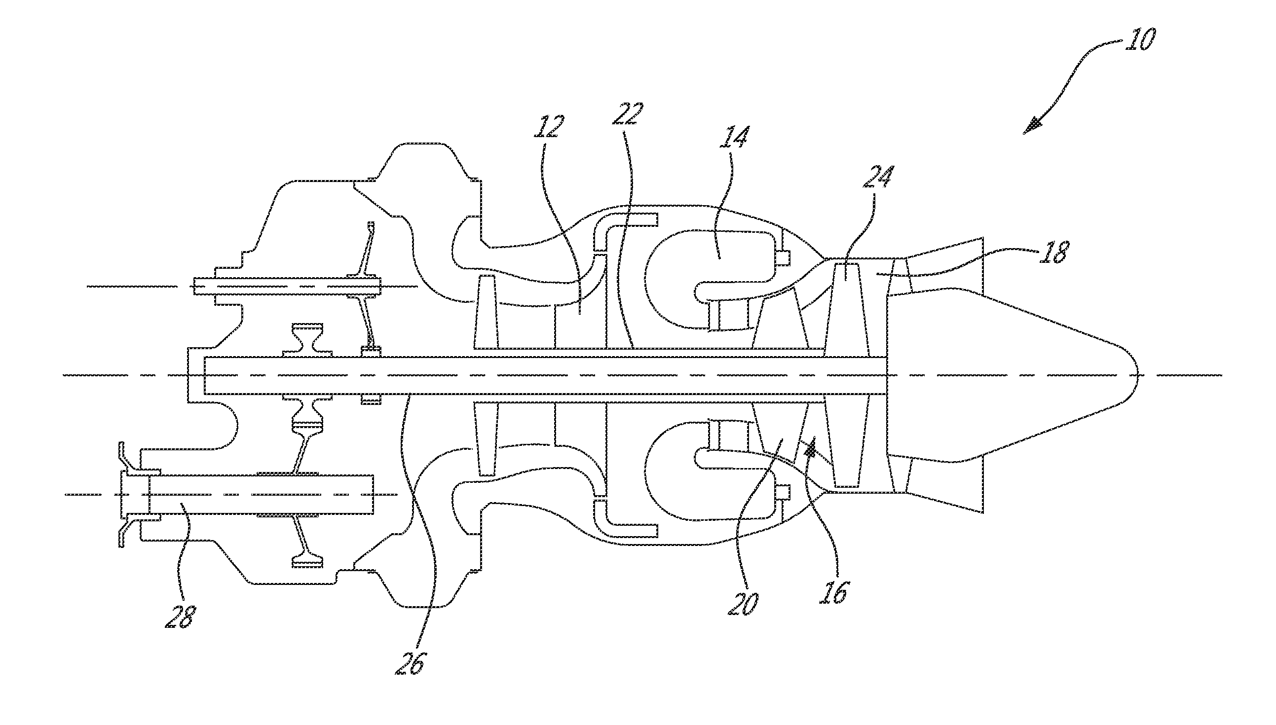
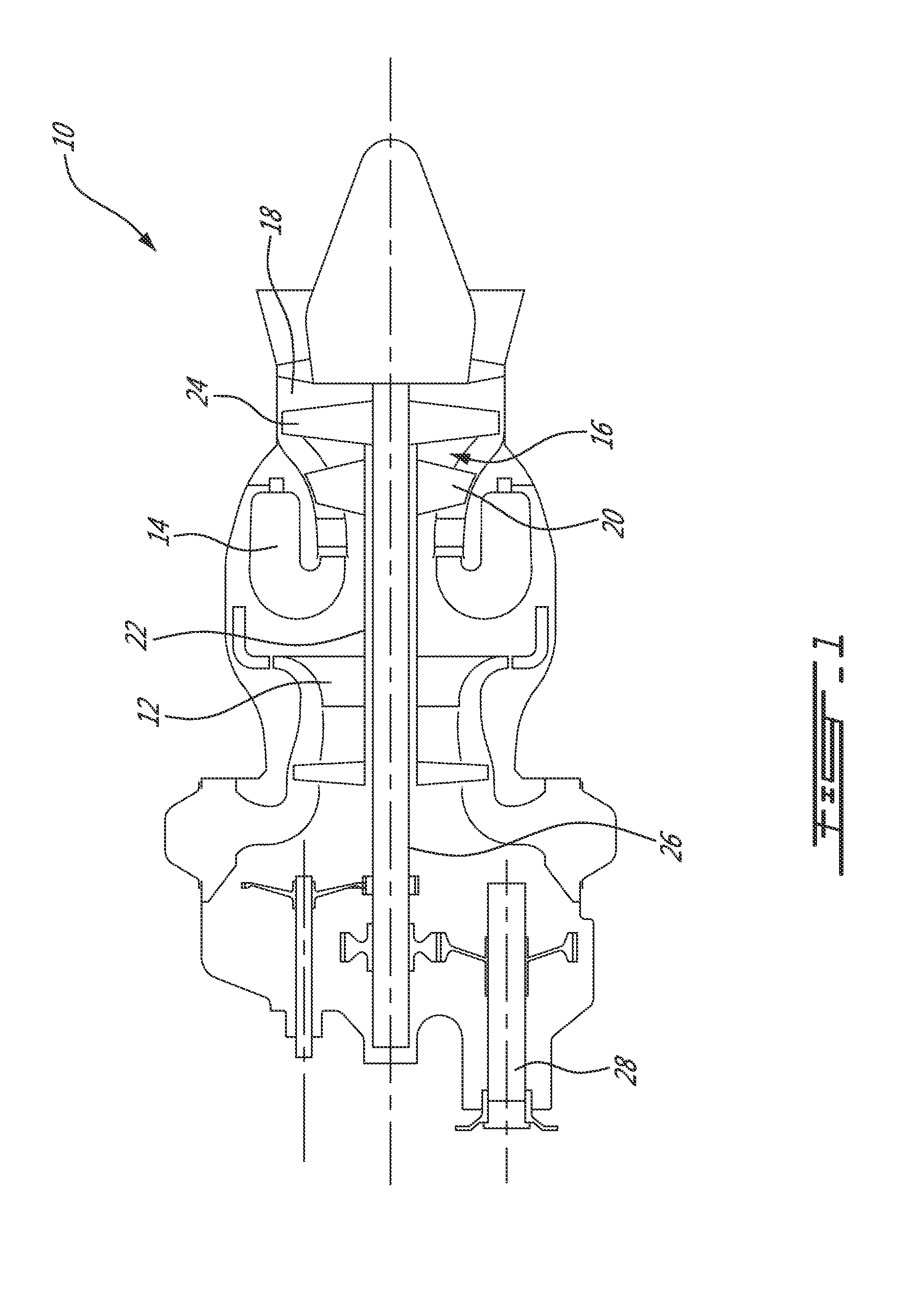
[0015]FIG. 1 illustrates a gas turbine engine 10 of a type preferably provided for use in subsonic flight, generally comprising in serial flow communication, a compressor section 12 for pressurizing the air, a combustor 14 in which the compressed air is mixed with fuel and ignited for generating an annular stream of hot combustion gases, and a turbine section 16 for extracting energy from the combustion gases. The combustion gases flowing out of the combustor 14 circulate through the turbine section 16 and are expelled through an exhaust duct 18. The turbine section 16 includes a compressor turbine 20 in driving engagement with the compressor section 12 through a high pressure shaft 22, and a power turbine 24 in driving engagement with a power shaft 26. The power shaft 26 is in driving engagement with an output shaft 28 through a reduction gearbox (not shown).

[0016]Although illustrated as a turboshaft engine, the gas turbine engine 10 may alternatively be another type of engine, for...


PUM


Abstract

There is provided a system and method for controlling an engine. A request signal indicative of a demand for the engine to output a required power level is first receive. A position control signal is then generated in response to the request signal. The position request signal is indicative of a first request for adjusting a present position of a variable geometry mechanism of the engine towards a commanded position to achieve the required power level. An acceleration rate control signal is further generated on the basis of the position control signal. The acceleration rate control signal is indicative of a second request for adjusting an acceleration rate of the engine in accordance with the commanded position of the variable geometry mechanism. The position control signal and the acceleration rate control signal are then output to the engine.

Description

TECHNICAL FIELD[0001]The application relates generally to the control of gas turbine engines, and more particularly to controlling transient aspects thereof.BACKGROUND OF THE ART[0002]During aircraft operations consisting of rapid engine transitions from low to high power levels, it is desirable to reduce the response time of the engine in order to achieve a required power. For this purpose, inlet mass flow can be increased by accelerating the gas generator of the engine, thereby increasing the engine's power. This may be achieved by a variety of techniques. For instance, a bleed valve may be actuated either actively or passively. However, active actuation of the bleed valve adds weight to the engine while passive actuation increases the gas path temperature and decreases the gas generator speed of the engine. The running line of the engine can alternatively be lowered to improve transient engine performance. This may however result in a decrease in the overall efficiency, an increa...

Claims


Application Information

Patent Timeline
Patent Type & Authority Patents(United States)
IPC IPC(8): F02D29/02F02C9/54
CPCF02D29/02F02C9/54F05D2270/335F05D2270/304F05D2270/044F05D2270/053
Inventor BELLEVILLE, FRANCOISBEAUCHESNE-MARTEL, PHILIPPEMORGAN, KEITH
Owner PRATT & WHITNEY CANADA CORP
Why Eureka
Try Eureka