Detecting patterns with proximity sensors

a proximity sensor and pattern detection technology, applied in the field of electronic display devices, can solve the problem that devices do not account for the movement of objects, and achieve the effect of facilitating determination and facilitating distribution

Active Publication Date: 2016-04-26
AVAYA INC
View PDF18 Cites 0 Cited by
  • Summary
  • Abstract
  • Description
  • Claims
  • Application Information

AI Technical Summary

Benefits of technology

[0003]The inventors of this subject matter have recognized that a message is displayed more effectively on a display device, if it is displayed according to the movement pattern of an object. For example, a message is exposed to a person for a longer duration of time, if the message is shifted (according to, or) along with the person while she is passing-by the display device. Furthermore, the display device could be used to simultaneously display multiple messages for multiple persons. Also, physical characteristics of a person could be determined from the movement pattern of a person. For example, movement pattern of hands, legs and neck of a kid of height less than 3 feet is different than movement pattern of an adult of height more than 5 feet. Ability to determine physical characteristics is advantageous, because the physical characteristics could be used for selecting messages for displaying. The above considerations, while displaying a message, provide unprecedented advantages, particularly, when commercial messages are being displayed.
[0006]Output from a detector is an indicative of the activities around the detector. In some embodiments, if the detector provides a steady square wave output pattern, this means one or more objects around the detector are in motion. In some embodiments, if the detector provides a step function output, which is steady at logical high then it means an object is in front of the detector. In some other embodiments, if the detector provides a step function which is steady at logical low, then it means no object is in front of the detector. The present subject matter exploits the temporal pattern of the outputs of the detector / s for displaying messages more effectively.

Problems solved by technology

These devices do not account for the movement of the object.

Method used


Image

  • Detecting patterns with proximity sensors
  • Detecting patterns with proximity sensors
  • Detecting patterns with proximity sensors

Examples


Embodiment Construction

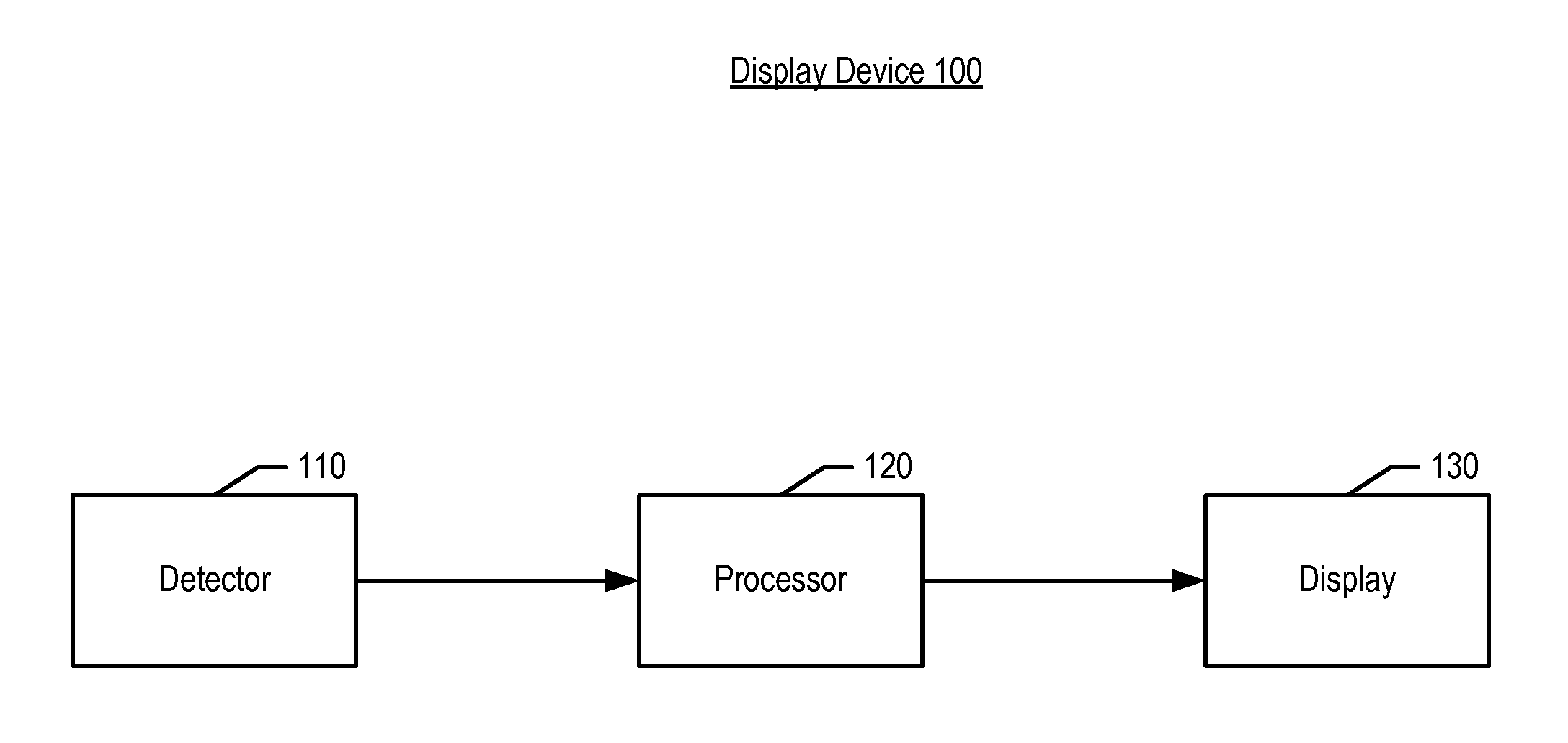
[0014]FIG. 1 depicts a schematic diagram of display device 100. Display device 100 comprises detector 110, processor 120 and display 130. It will be clear to those skilled in the art, after reading this disclosure, how to make and use alternative embodiments of the present invention wherein, display device 100 comprises more or less than above recited elements.

[0015]In some embodiments, detector 110 is a proximity detector. In some embodiments, detector 110 is an infra-red detector. In some other embodiments, detector 110 is an ultrasound detector. In some other embodiments, detector 110 is combination of both infra-red and ultrasound detectors. In some other embodiments, detector 110 is an array of proximity detectors. For sake of brevity and clarity, the illustrative embodiment describes display device 100 wherein detector 110 is one or more proximity detectors, however a person skilled in the art would know, after reading this specification, how to use other type of detectors for...


PUM


Abstract

A method, system, and computer-readable storage medium for displaying a message on a display according to a movement pattern of an object. The system first receives a first signal that indicates a presence of an object at a first location with respect to a display. Based on the first signal, the system then selects a message to display at the display. Finally, the system displays the message at the display based, at least in part, on a first temporal pattern associated with the first signal.

Description

FIELD OF THE INVENTION[0001]The present invention relates to display devices in general, and more particularly, to an electronic display device.BACKGROUND OF THE INVENTION[0002]Advancement in technology has brought message displaying techniques from placards to electronic display devices. Generally, most of the electronic display devices display a message regardless, whether the message is being watched / read by anyone. Some other devices display messages only when an object is in their close proximity.SUMMARY OF THE INVENTION[0003]The inventors of this subject matter have recognized that a message is displayed more effectively on a display device, if it is displayed according to the movement pattern of an object. For example, a message is exposed to a person for a longer duration of time, if the message is shifted (according to, or) along with the person while she is passing-by the display device. Furthermore, the display device could be used to simultaneously display multiple messa...

Claims


Application Information

Patent Timeline
Patent Type & Authority Patents(United States)
IPC IPC(8): G08B21/00G06F3/01G06F1/32
CPCG06F1/3231G06F3/017Y02B60/1289Y02D10/00
Inventor KASHI, RAMANUJAN
Owner AVAYA INC
Why Eureka
Try Eureka