Image capturing system having a virtual switch on a surface of a base of a mounting stand

a technology of image capture system and mounting stand, which is applied in the field of image capture system, can solve the problems of user burden, difficulty in adjusting the position of the mounting stand,

Active Publication Date: 2016-04-26
PFU LTD
View PDF48 Cites 4 Cited by
  • Summary
  • Abstract
  • Description
  • Claims
  • Application Information

AI Technical Summary

Benefits of technology

[0108]An image capturing system of the invention provides the advantage of having improved operability of a function executable by an imaging unit and greater facility of setting the imaging unit when the function is executed.

Problems solved by technology

As a result, there is a concern that a facility of operation may be impaired.
However, some sort of drudgery is required for physical connection at every placement of the imaging unit on the mounting stand.
Such drudgery of setting the imaging unit to the mounting stand could be burdensome for a user.

Method used


Image

  • Image capturing system having a virtual switch on a surface of a base of a mounting stand
  • Image capturing system having a virtual switch on a surface of a base of a mounting stand
  • Image capturing system having a virtual switch on a surface of a base of a mounting stand

Examples


first embodiment

[0028

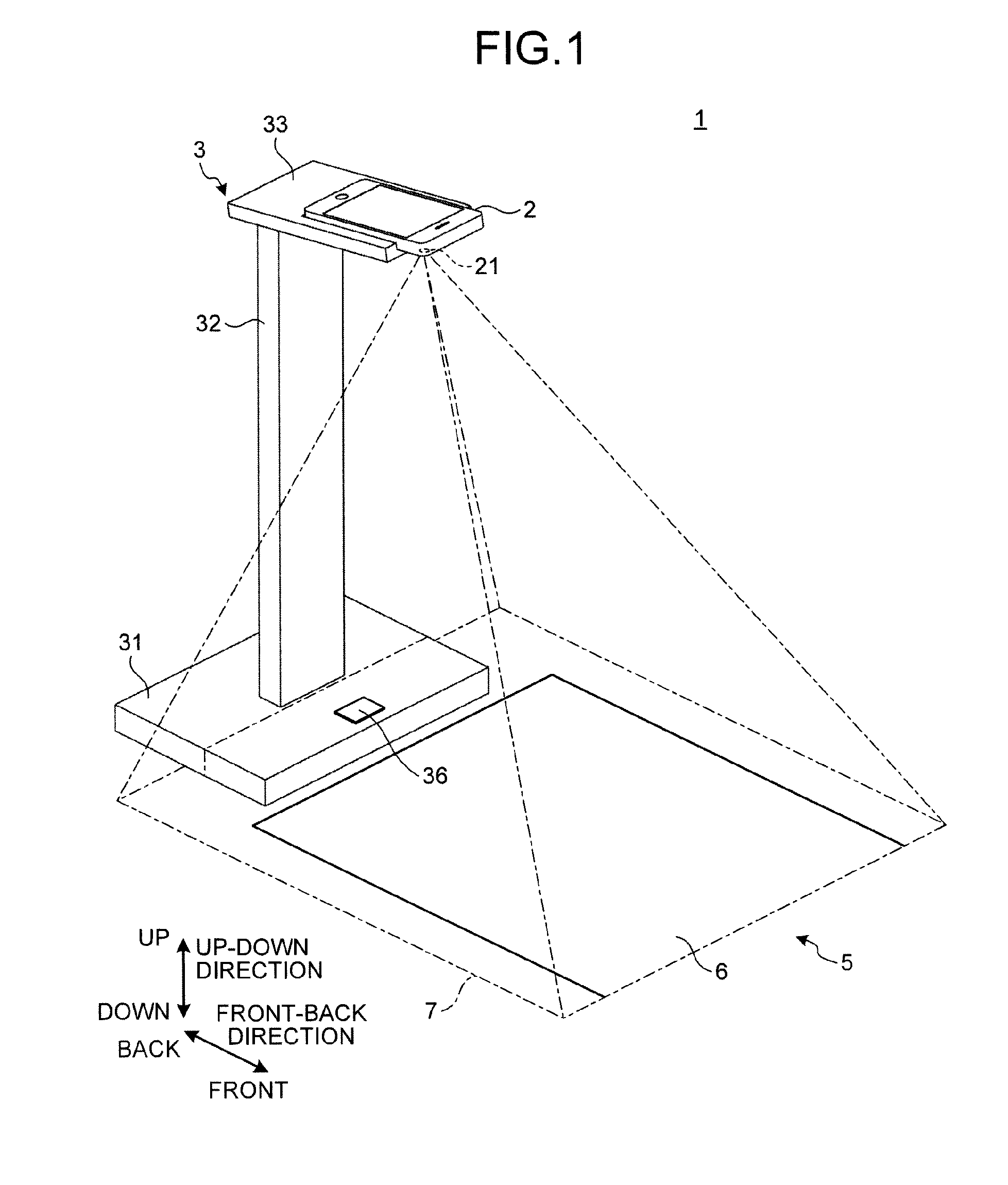
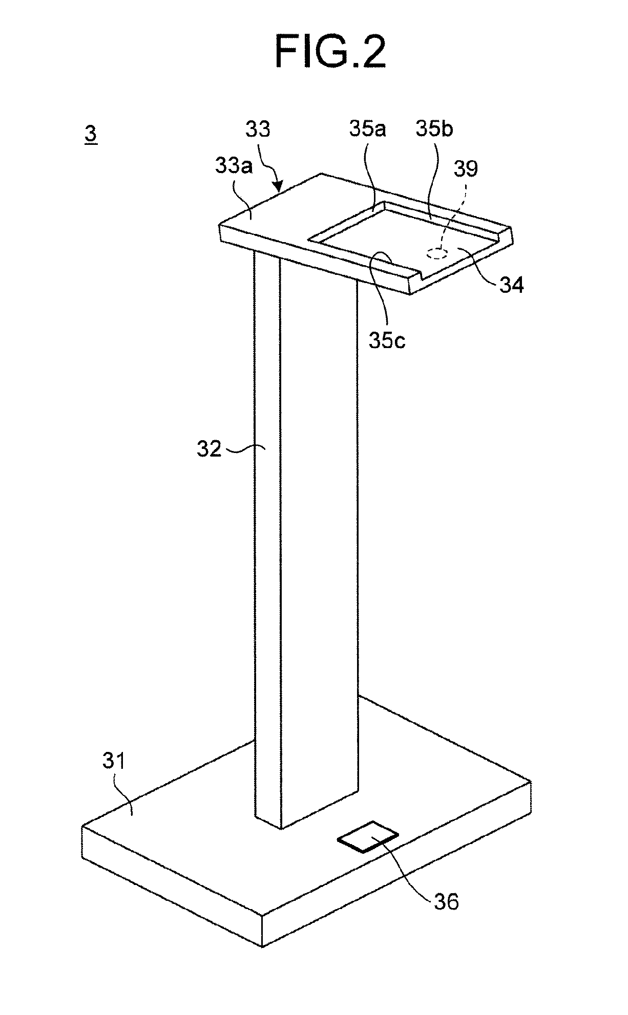
[0029]A first embodiment of the invention is described with reference to FIGS. 1 to 6B. The structure of an image capturing system according to the first embodiment is described with reference to FIGS. 1 to 3. FIG. 1 is a perspective view illustrating a schematic structure of the image capturing system in the first embodiment. FIG. 2 is a perspective view of a mounting stand in FIG. 1. FIG. 3 is a functional block diagram of the image capturing system illustrated in FIG. 1.

[0030]This image capturing system 1 is a scanning system that performs scanning operation to generate image data of a medium 6, which is set on a medium setting surface 5 as a reading target, by capturing image of the medium 6 by a predetermined imaging unit from above. In the embodiment, the description is made with a smartphone 2 having a camera function as an example of the imaging unit.

[0031]As illustrated in FIG. 1, the image capturing system 1 includes the smartphone 2 and a mounting stand 3 on which th...

second embodiment

[0080

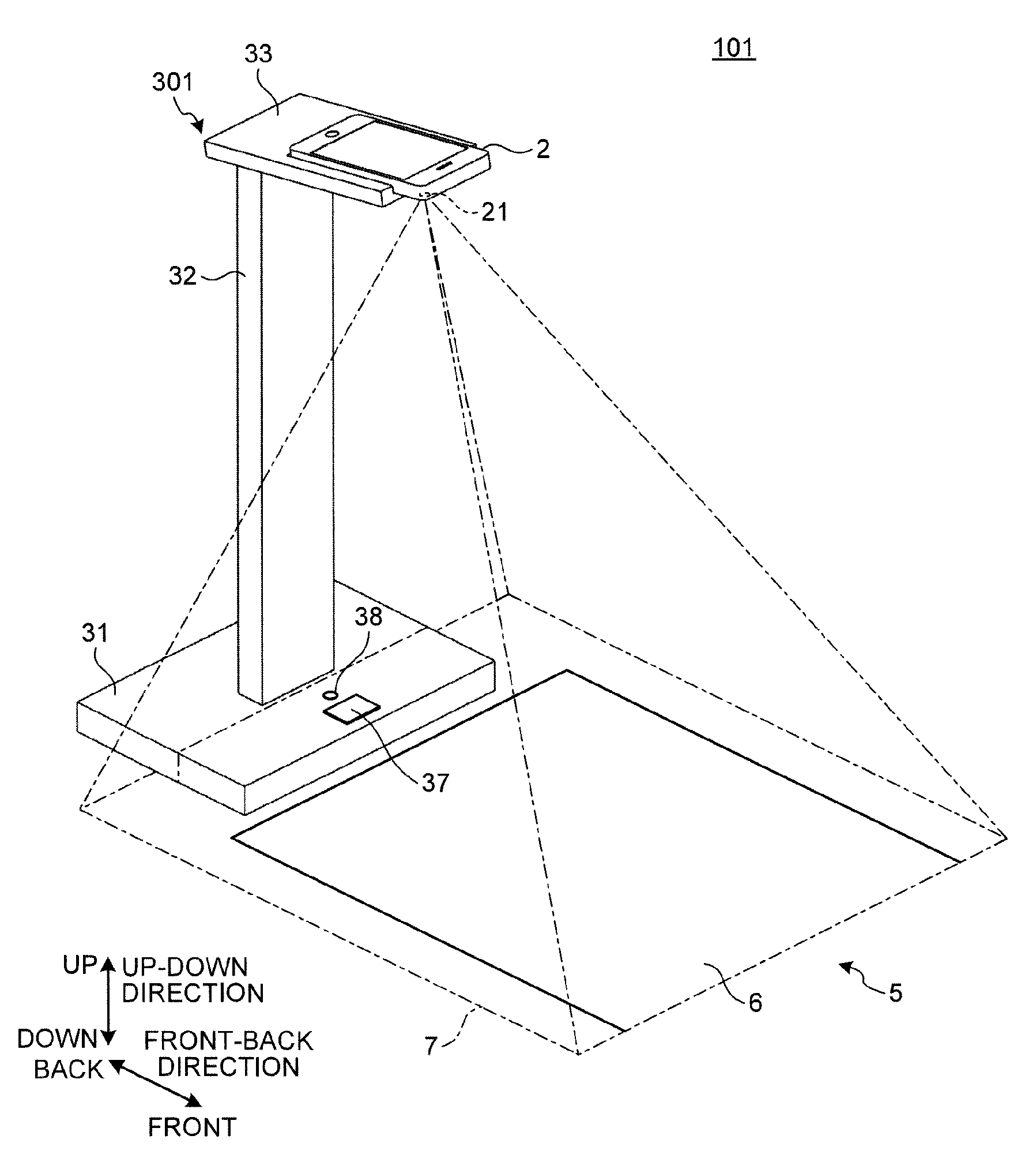
[0081]A second embodiment of the invention is described below with reference to FIGS. 12 to 14. FIG. 12 is a perspective view illustrating a schematic structure of an image capturing system according to the second embodiment. FIG. 13 is a functional block diagram of the image capturing system illustrated in FIG. 12. FIG. 14 is a flowchart illustrating medium imaging processing performed by the image capturing system in the second embodiment.

[0082]As illustrated in FIG. 12, this image capturing system 101 of the embodiment differs from the image capturing system 1 of the first embodiment in that, as the input units of the scanning operation, a scanning switch 37 and a communication LED 38 are provided to the base 31 of a mounting stand 301.

[0083]As illustrated in FIG. 13, the scanning switch 37, the communication LED 38, and the lighting LED 39 are electrically connected to a controller 40 provided inside the mounting stand 301.

[0084]The scanning switch 37 is an input unit that ...


PUM


Abstract

An image capturing system includes a smartphone serving as an imaging unit, and a mounting stand to be disposed on a medium setting surface on which a medium serving as a reading target is set. The mounting stand has a placement surface on which the smartphone is placed at a position allowing the smartphone to image the medium set on the medium setting surface. When generating a starting trigger based on image information of an imaging area in the state where the smartphone is placed on the mounting stand, the smartphone executes a function (scanning operation) associated with the starting trigger.

Description

CROSS-REFERENCE TO RELATED APPLICATIONS[0001]This application is based upon and claims the benefit of priority from Japanese Patent Application No. 2012-274586, filed on Dec. 17, 2012, the entire contents of which are incorporated herein by reference.BACKGROUND OF THE INVENTION[0002]1. Field of the Invention[0003]The present invention relates to an image capturing system.[0004]2. Description of the Related Art[0005]There are needs of performing scanning operation to capture images of desired media such as books, magazines, and documents using mobile imaging units such as cellular phones, smartphones, and digital cameras, and acquire image data. For performing such scanning operation, a mounting stand is provided on which the imaging unit is placed in such a manner that the imaging unit can image a medium setting surface from above (e.g., refer to Japanese Patent Application Laid-open No. 2005-99708).[0006]When the scanning operation is performed using the imaging unit, the imaging u...

Claims


Application Information

Patent Timeline
Patent Type & Authority Patents(United States)
IPC IPC(8): H04N5/235H04N5/225H04N1/195H04N1/00
CPCH04N5/2354H04N1/00381H04N5/225H04N5/2251H04N5/235H04N1/19594H04N1/00307H04N2201/0436H04N23/60H04N23/74H04N23/00H04N23/70
Inventor KASAHARA, YUKI
Owner PFU LTD
Why Eureka
Try Eureka