Wire bonding apparatus and bonding method

a wire bonding and wire bonding technology, applied in electrical devices, semiconductor devices, semiconductor/solid-state device details, etc., can solve problems such as the inability to achieve high-speed bonding

Active Publication Date: 2016-05-10
SHINKAWA CO LTD
View PDF21 Cites 8 Cited by
  • Summary
  • Abstract
  • Description
  • Claims
  • Application Information

AI Technical Summary

Benefits of technology

[0027]The present invention provides an advantageous effect of providing a wire bonding apparatus capable of performing high-speed wedge wire bonding.

Problems solved by technology

However, rotating the bonding head or the bonding stage poses a problem of increasing a size of a bonding apparatus as a whole, as well as a problem of a slower bonding speed, which results in an inability of high-speed bonding.

Method used


Image

  • Wire bonding apparatus and bonding method
  • Wire bonding apparatus and bonding method
  • Wire bonding apparatus and bonding method

Examples


Embodiment Construction

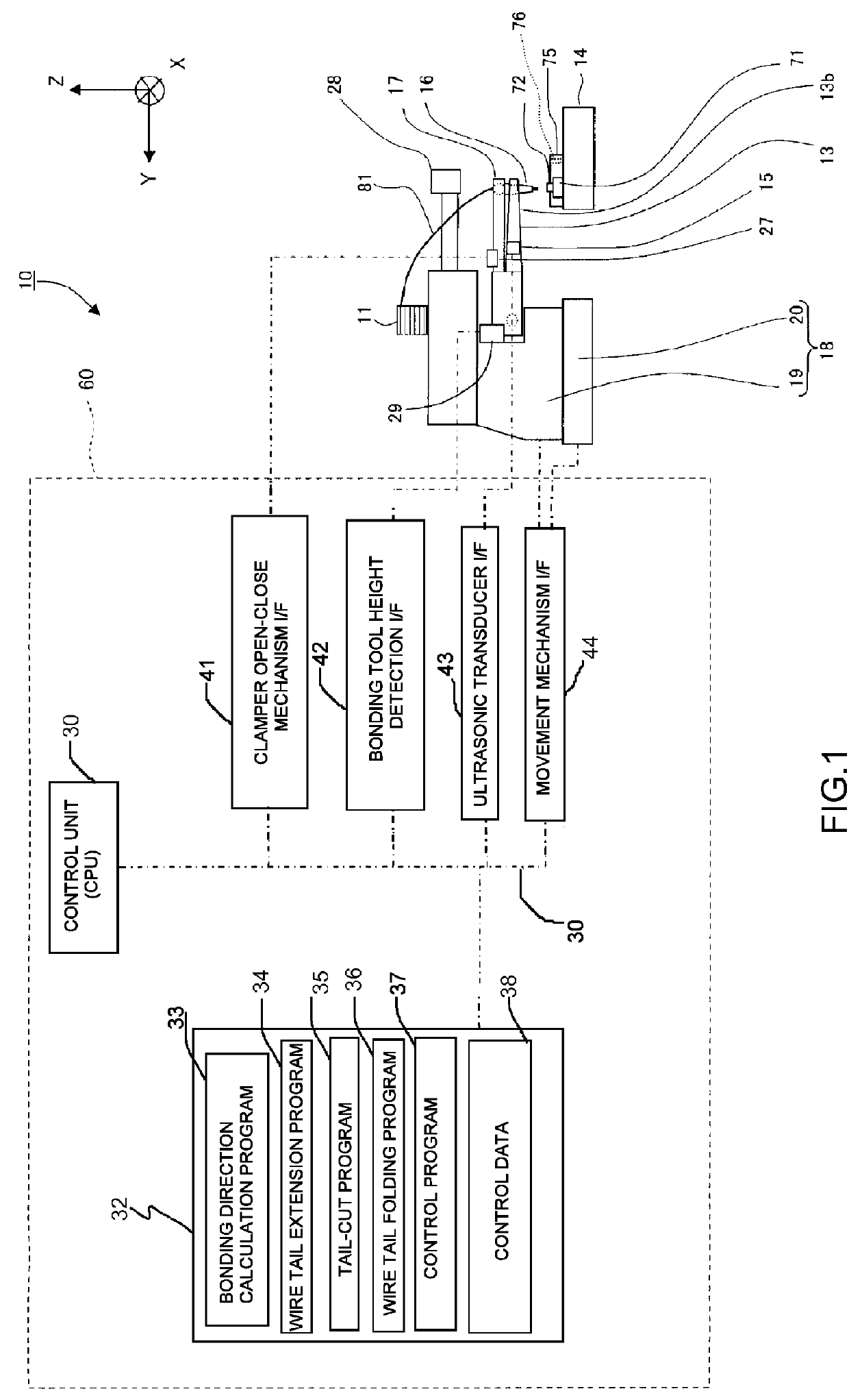
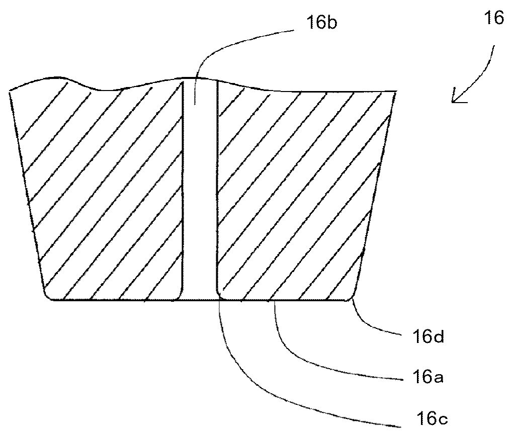
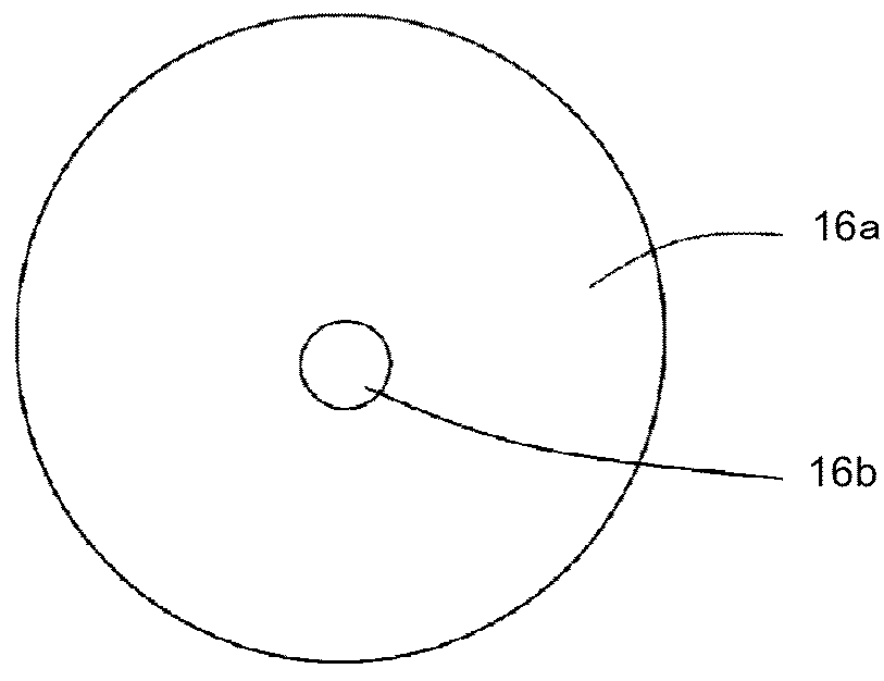
[0103]Hereinafter, a wire bonding apparatus 10 according to embodiments of the present invention will be described with reference to the drawings. In FIG. 1, signal lines are shown by alternate long and short dash lines. As illustrated in FIG. 1, the wire bonding apparatus 10 is configured such that a bonding head 19 is placed on an XY table 20, and a bonding arm 13 is attached to the bonding head 19. The bonding arm 13 is configured to be driven by a Z motor about a rotational center, and such that an ultrasonic horn 13b is attached to a tip of the arm, and a tip of the ultrasonic horn 13b moves closer to and away from a pad surface of a chip 72 as a bonding surface in an arc. The tip of the ultrasonic horn 13b moves in a Z direction, which is an up-down direction, near the pad surface of the chip 72 or a surface of a substrate 71. To the tip of the ultrasonic horn 13b, a bonding tool 16 is attached. The XY table 20 and the bonding head 19 constitute a movement mechanism 18, and th...


PUM


Abstract

Provided is a wire bonding apparatus capable of performing high-speed wedge wire bonding, the apparatus including: a bonding tool having a through hole and a pressing surface for pressing a wire; a clamper for holding the wire; and a control unit. The control unit includes: wire tail extension unit that moves the bonding tool, after wedge bonding of the wire to a first lead, upward and along a second straight line connecting a second pad and a second lead, and causes the wire to extend from the through hole in a direction along the second straight line from the second pad to the second lead; and tail cut unit that, after causing the wire tail to extend, cuts the wire tail by moving the bonding tool in the direction along the second straight line connecting the second pad and the second lead while the clamper is closed.

Description

TECHNICAL FIELD[0001]The present invention relates to a structure of wire bonding apparatuses and a bonding method using such a bonding apparatus.BACKGROUND ART[0002]Wire bonding apparatuses are commonly used for connecting a chip and a substrate. Such wire bonding apparatuses include two types: ball wire bonding apparatuses and wedge wire bonding apparatuses. A ball wire bonding apparatus connects a plurality of pads of a chip respectively with a plurality of leads of a substrate by repeating: forming an initial ball from a wire extending from a tip of a capillary by causing a spark and such; bonding the initial ball as a bonding ball to a pad of the chip by pressing the initial ball onto the pad and applying ultrasonic vibration to the initial ball; looping the wire toward a lead of the substrate while paying out the wire from the capillary; bonding the wire by pressing the wire to the lead of the substrate; cutting the wire after moving the capillary upward and extending a wire t...

Claims


Application Information

Patent Timeline
Patent Type & Authority Patents(United States)
IPC IPC(8): H01L23/00H01L25/065
CPCH01L24/85H01L24/78H01L24/45H01L2224/49175H01L2224/73265H01L2224/78301H01L2224/78802H01L2224/85047H01L2224/85181H01L2224/85186H01L2224/85205H01L2225/0651H01L2225/06506H01L2225/06568H01L2924/01082H01L2924/12041H01L24/48H01L24/49H01L25/0655H01L25/0657H01L2224/04042H01L2224/05554H01L2224/32145H01L2224/32225H01L2224/32245H01L2224/45015H01L2224/45124H01L2224/45144H01L2224/48091H01L2224/48145H01L2224/48227H01L2224/48247H01L2224/48472H01L2224/49171H01L2224/49173H01L2924/00H01L2924/00012H01L2924/00014H01L24/73H01L2224/4554H01L2224/7855H01L2224/78621H01L2224/78804H01L2224/851H01L2224/95
Inventor HAGIWARA, YOSHIHITOSEKINE, NAOKITAKAHASHI, KOICHINAGASHIMA, YASUONAKAZAWA, MOTOKI
Owner SHINKAWA CO LTD
Why Eureka
Try Eureka