Auto cleaning toilet seat and method of use

a toilet seat and automatic cleaning technology, applied in the field of toilet systems, can solve the problems of increasing the risk of failure of assembly, and increasing the maintenance and installation time of many components, so as to reduce the maintenance and installation time of an automatic cleaning assembly, reduce the risk of failure, and save energy

Active Publication Date: 2016-05-17
AUTO CLEANING TOILET SEAT USA LLC
View PDF5 Cites 9 Cited by
  • Summary
  • Abstract
  • Description
  • Claims
  • Application Information

AI Technical Summary

Benefits of technology

[0005]With the foregoing and other objects in view, there is provided, in accordance with the invention, an automatic cleaning toilet seat assembly that solves the above-described disadvantageous and includes its implementation in connection with a toilet having a toilet seat including a front end, a back end, a top surface, and an inner and an outer circumferential surface. The assembly includes a cover with a first position and a second position along a translation path. The first position includes the cover surrounding the toilet seat to define a conduit spanning from the back end of the toilet seat to the front end of the toilet seat and with a width spanning approximately from the inner circumferential surface to the outer inner circumferential surface. The second position includes the cover removed from above a portion of the toilet seat. The cover defines at least one liquid aperture fluidly coupled, through a fluid channel, to a liquid source with a liquid matter and defines at least one gas aperture in fluid communication with the conduit and fluidly coupled, through a gas channel, to a gas source with a gaseous matter. The assembly also has an electrical system operable to cause (1) the liquid matter to discharge onto a portion of the toilet seat proximal to the back end of the toilet seat through the at least one liquid aperture and (2) the gaseous matter to discharge through the at least one gas aperture at a speed sufficient to transport the liquid matter through the conduit, when the cover is in the first position. This embodiments provides an efficient and effective cleaning process that conserves energy and minimizes the maintenance and installation of an automatic cleaning assembly.
[0014]In accordance with another feature, an embodiment of the present invention includes the cover including a plurality of liquid apertures fluidly coupled, through a plurality of fluid channels, to the liquid source and a plurality of gas apertures fluidly coupled, through a plurality of gas channels, to the gas source. The aforementioned electrical system is then operable to cause the liquid matter to discharge through the plurality of liquid apertures onto the portion of the toilet seat proximal to the back end of the toilet seat in the first and second conduits and to cause the gaseous matter to discharge through the plurality of gas apertures at a speed in each of the first and second conduits sufficient to transport the liquid matter from the portion of the toilet seat proximal to the back end of the toilet seat to the front end of the toilet seat. This liquid matter may derive (and its corresponding pressure) from the lines utilized with the building to which the toilet is attached.
[0018]In accordance with an additional feature, an embodiment of the present invention includes a distance separating the top surface of the toilet seat and an upper surface of the cover. The distance separating the top surface of the toilet seat and the upper surface of the cover tapers as the conduit spans from the back end of the toilet seat to the front end of the toilet seat to facilitate air / fluid flow in the conduit.

Problems solved by technology

These numerous components require a great deal of user time spent in maintenance and installation.
Moreover, many of these assemblies have components that rotate and move when in operation such that they are more susceptible to failure.
Not only are these assemblies more susceptible to failure, they are also more expensive and difficult to manipulate for precise control of the assembly during the cleaning process.
For example, some known assemblies have rotating arms that clean the toilet seat but these arms are not able to be controlled or optimized to produce various cleaning cycles desirable for a particular user.
Some known assemblies for automatically cleaning a toilet seat provide multiple discharge locations of liquid and gas, e.g., air, onto a toilet seat, thereby requiring more parts and a more unattractive assembly as it is perceived by the view public.
Because of the amount of parts associated with these assemblies, they are generally expensive and require more time / cost to install and to maintain.
Moreover, many of those known toilet seat cleaning devices utilize complex and expensive mechanical devices to discharge the fluid onto the toilet seat and remove it from the same.

Method used


Image

  • Auto cleaning toilet seat and method of use
  • Auto cleaning toilet seat and method of use
  • Auto cleaning toilet seat and method of use

Examples


Embodiment Construction

[0057]It is evident that an invention such as the automatic toilet seat-cleaning system claimed in the present application is quite desirable because it disinfects the toilet seat before use. The claimed invention is also quite desirable because it provides an apparatus that washes and dries the anus and adjacent body opening areas of a user after using a toilet. In addition, the claimed invention can be used in circular and / or oval shape toilet bowls. Furthermore, the claimed invention is volumetrically efficient, of a durable and reliable construction, and it is inexpensive to manufacture and maintain while retaining its effectiveness.

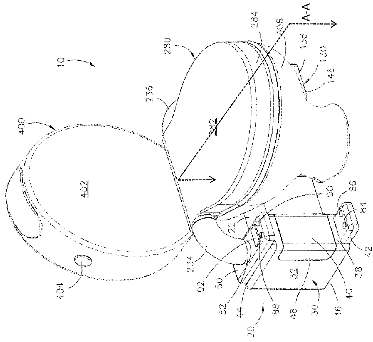
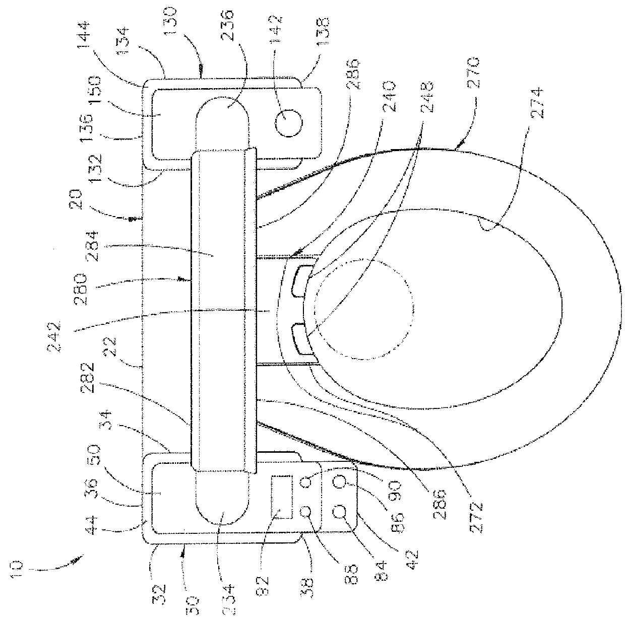
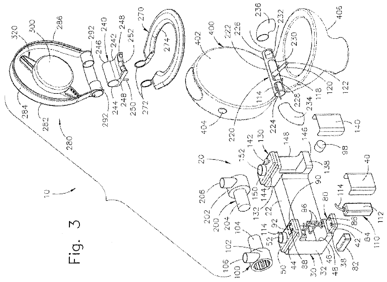
[0058]Referring now to the drawings, the present invention is a combined automatic toilet self-cleaning and user hygienic system and is generally referred to with numeral 10. It can be observed that it basically includes housing assembly 20, electrical system 80, liquid matter system 110, turbine assemblies 100 and 200, manifold assembly 220, manifol...


PUM


Abstract

An automatic cleaning toilet seat assembly with a cover surrounding a toilet seat to define a conduit spanning from a back end to a front end of a toilet seat and with a width approximately from the inner circumferential surface to the outer circumferential surface, defining at least one liquid aperture fluidly coupled to a liquid source with a liquid matter, and defining at least one gas aperture in fluid communication with the conduit and fluidly coupled to a gas source with a gaseous matter, the assembly also having an electrical system operable to cause the liquid matter to discharge onto a portion of the toilet seat proximal to the back end of the toilet seat through the at least one liquid aperture and to cause the gaseous matter to discharge through the at least one gas aperture at a speed sufficient to transport the liquid matter through the conduit.

Description

CROSS-REFERENCE TO RELATED APPLICATION[0001]This application is a continuation-in-part and claims priority to U.S. application Ser. No. 14 / 007,893, filed on Sep. 26, 2013, which claims priority to PCT Application No. PCT / US12 / 42269, filed Jun. 13, 2012, which claims priority to U.S. application Ser. No. 13 / 253,197, filed on Oct. 5, 2011, now issued as U.S. Pat. No. 8,365,317, which is a continuation-in-part of U.S. application Ser. No. 12 / 823,873, filed on Jun. 25, 2010, now issued as U.S. Pat. No. 8,060,953; the entirely of these applications and patents are incorporated by reference. This application is also a continuation-in-part and claims priority to U.S. application Ser. No. 13 / 863,601, filed on Apr. 16, 2013.FIELD OF THE INVENTION[0002]The present invention relates to toilet systems, and more particularly, to an automatic toilet seat cleaning assembly.BACKGROUND OF THE INVENTION[0003]There are many other known toilet seat washing assemblies. Most of these assemblies employ th...

Claims


Application Information

Patent Timeline
Patent Type & Authority Patents(United States)
IPC IPC(8): A47K13/00E03D9/00A47K13/30E03D9/08
CPCE03D9/08E03D9/002A47K13/302
Inventor DORRA, MAXIMO
Owner AUTO CLEANING TOILET SEAT USA LLC
Why Eureka
Try Eureka