Snips operable by a single hand

a single-hand, snip technology, applied in the field of snips, can solve problems such as inconvenience for users

Inactive Publication Date: 2016-05-24
TSAI WEN CHIAO
View PDF14 Cites 15 Cited by
  • Summary
  • Abstract
  • Description
  • Claims
  • Application Information

AI Technical Summary

Problems solved by technology

Thus, the snips must be operated with both hands to switch between the open position and the closed position, causing inconvenience to the user.

Method used


Image

  • Snips operable by a single hand
  • Snips operable by a single hand
  • Snips operable by a single hand

Examples


Embodiment Construction

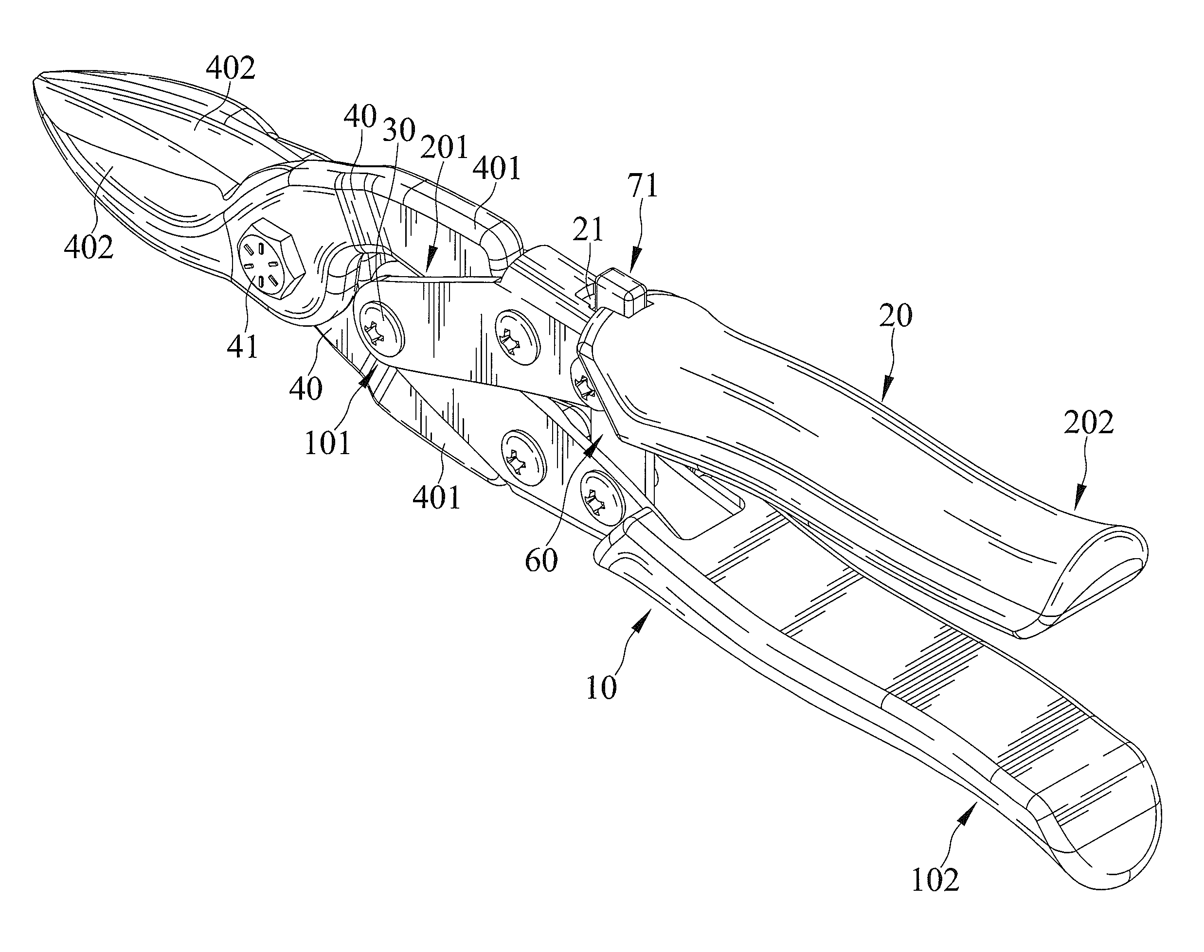
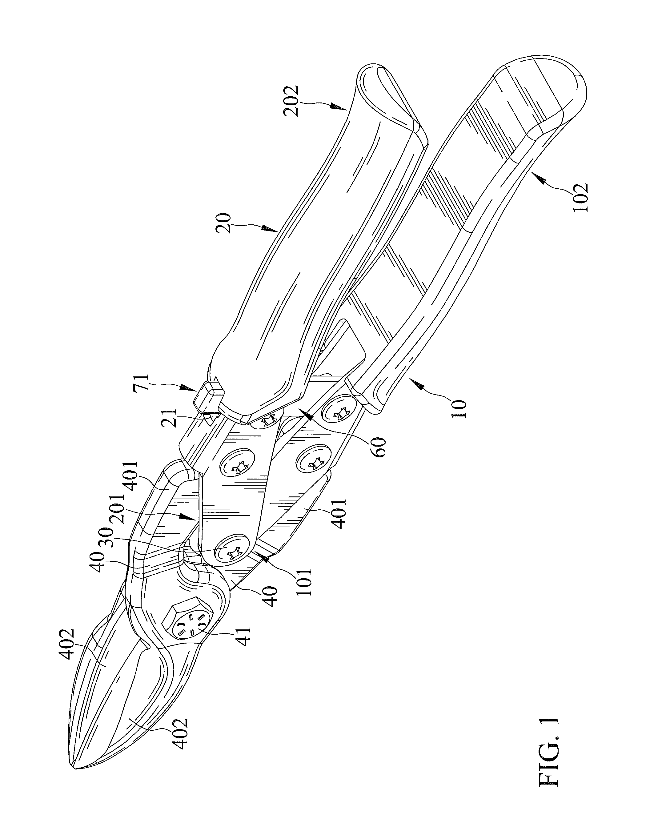
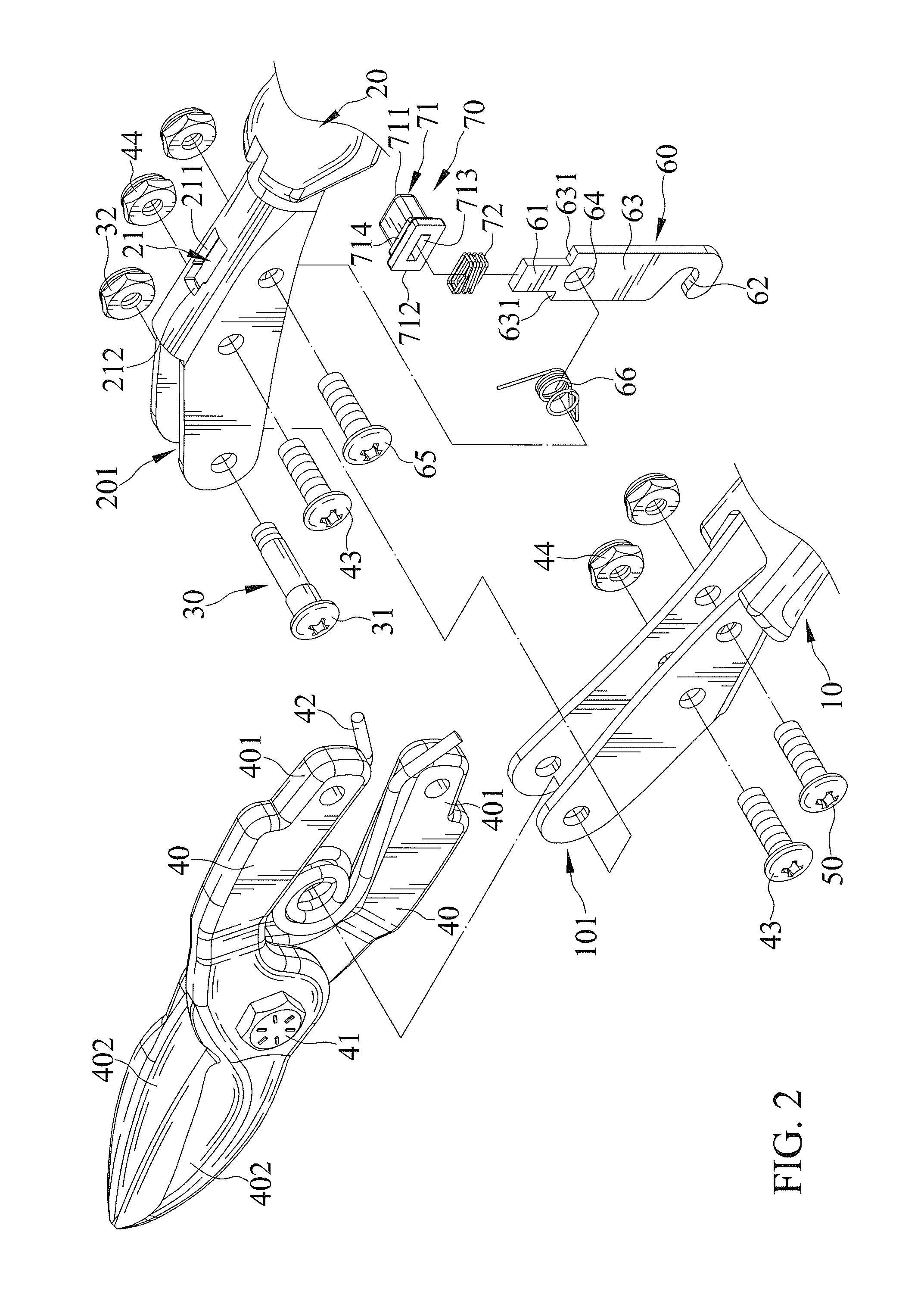
[0028]FIGS. 1-8 show snips operable by a single hand according to the present invention. According to the form shown, the snips includes a first handle 10, a second handle 20, a pivotal device 30, a pair of cutting members 40, a limiting member 50, a latch 60, and a positioning device 70. The first handle 10 and the second handle 20 are pivotably connected by the pivotal device 30 to switch between an open position and a closed position. The cutting members 40 are respectively connected to the first handle 10 and the second handle 20. The limiting member 50 extends through the first handle 10. The latch 60 is pivotably connected to the second handle 20 and is pivotable relative to the second handle 20 between a locking position and a release position under operation by a single hand of a user. When the latch 60 is in the locking position, the hook 62 engages with the limiting member 50, and the first handle 10 is not pivotable relative to the second handle 20. On the other hand, whe...


PUM


Abstract

Snips include first and second handles pivotably connected to each other. Each of a pair of cutting members includes a connecting end and a cutting end. The connecting ends of the cutting members are respectively connected to distal ends of the first and second handles. A latch is pivotably mounted to the second handle and extends through a through-hole in the second handle. When the latch is in a locking position, a protrusion of the latch is located in a first section of the through-hole, a hook of the latch engages with a limiting member on the first handle, and the first handle is not pivotable relative to the second handle. When the latch is in the release position, the protrusion is located in a second section of the through-hole, the hook disengages from the limiting member, and the first handle is pivotable relative to the second handle.

Description

BACKGROUND[0001]The present invention relates to snips and, more particularly, to snips operable by a single hand to switch between a locking position and a release position.[0002]U.S. Pat. No. 6,189,219 discloses multiple purpose compound action snips including a pair of handles mutually connected at a handle pivot and a pair of cutting blades connected to the handles. The blades are respectively attached to distal portions of the handles by two bolts. A latch is mounted to one of the bolts and can be engaged with the other bolt. The snips are in a closed position not allowing pivotal movement of the handles about the handle pivot when the latch engages with the other bolt. On the other hand, the snips are in an open position allowing pivotal movement of the handles about the handle pivot to permit the cutting blades to perform a cutting operation when the latch disengages from the other bolt.[0003]However, a user must hold the handles with one hand and engage the latch with the ot...

Claims


Application Information

Patent Timeline
Patent Type & Authority Patents(United States)
IPC IPC(8): B26B13/28A01G3/02B25B7/14B26B13/16
CPCB26B13/28A01G3/021B25B7/14B26B13/16B26B13/26
Inventor TSAI, WEN-CHIAO
Owner TSAI WEN CHIAO
Why Eureka
Try Eureka