
Transmission for vehicle

a technology for transmissions and vehicles, applied in the direction of gearing details, gearing, transportation and packaging, etc., can solve the problems of reducing the number of parts of the transmission, lowering the gear shift feeling, and lowering so as to improve the fuel ratio of the vehicle, prevent the diameter of the driving gear and the driving gear from increasing, and improve the performance of the transmission to the vehicle.

Active Publication Date: 2016-05-24
HYUNDAI MOTOR CO LTD
View PDF16 Cites 0 Cited by
  • Summary
  • Abstract
  • Description
  • Claims
  • Application Information

AI Technical Summary

Benefits of technology

[0014]Various aspects of the present invention are directed to providing a transmission for a vehicle by which mounting performance of the transmission to a vehicle can be improved and a fuel ratio of the vehicle can be improved by realizing a plurality of desired gear shift stages while preventing diameters of a driving gear and a driven gear from increasing, preventing a distance between shafts from increasing, and preventing the volume and weight of the transmission from increasing to secure a strength of the driving gear provided on a hollow shaft, and an excellent gear shift quality can be realized by overcoming a gear shift feeling lowering phenomenon due to a torque interruption phenomenon during gear shift.

Problems solved by technology

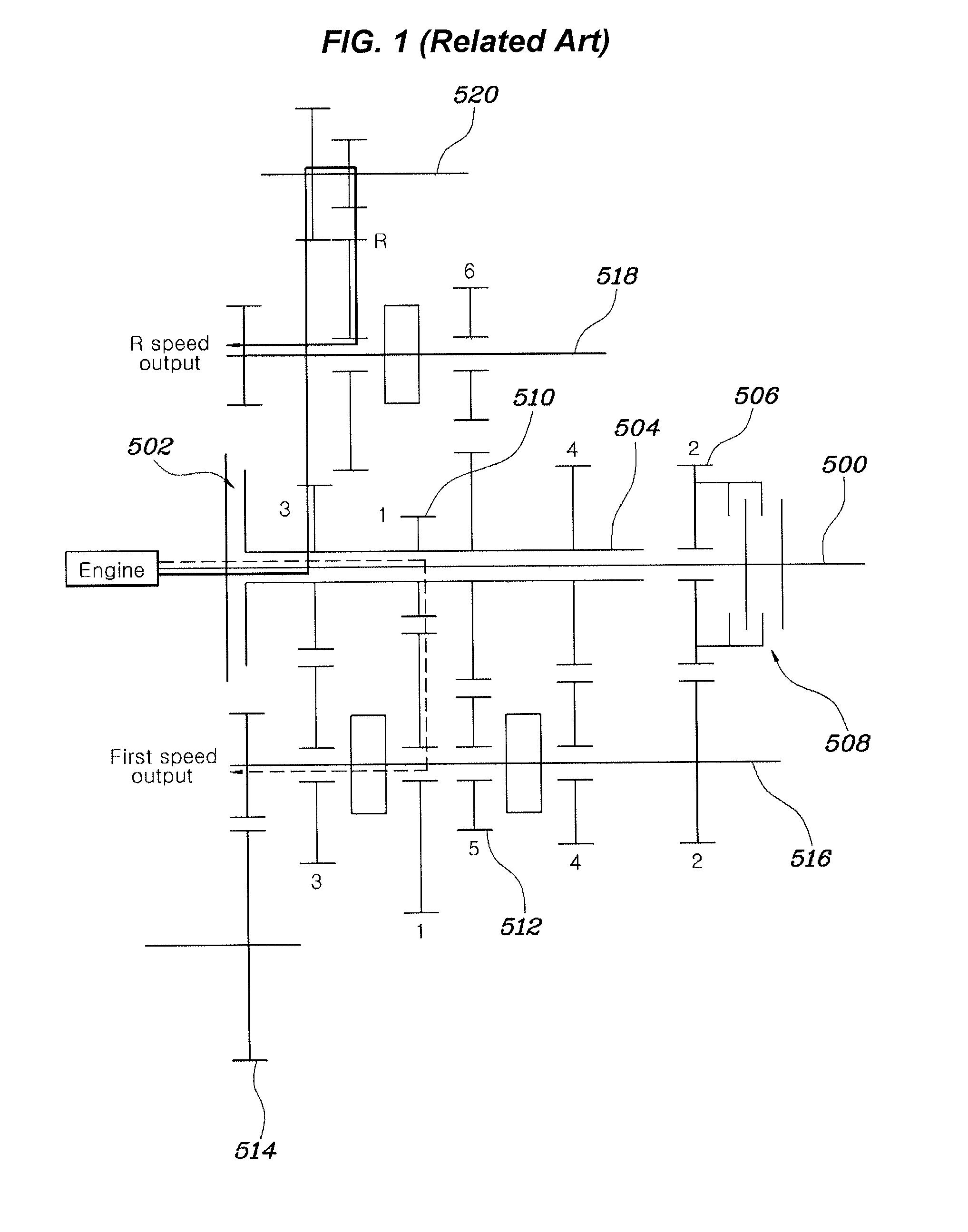
A main problem in development of transmissions mounted to vehicles is to reduce the number of parts of a transmission, the weight, overall length, and volume of the transmission.
The above-described synchronized gear type transmission essentially generates a torque interrupting phenomenon by which transmission of power is interrupted while a synchronizing unit is released from the previous gear shift and is coupled to a gear shift that will transmit power newly, which is a main cause of lowering a gear shift feeling.
The lowering of the gear shift feeling due to the cause becomes a big problem in lower stages such as first to third stages but a driver tends to feel the phenomenon relatively less at a high speed.

Method used


Image

  • Transmission for vehicle
  • Transmission for vehicle
  • Transmission for vehicle

Examples


first embodiment

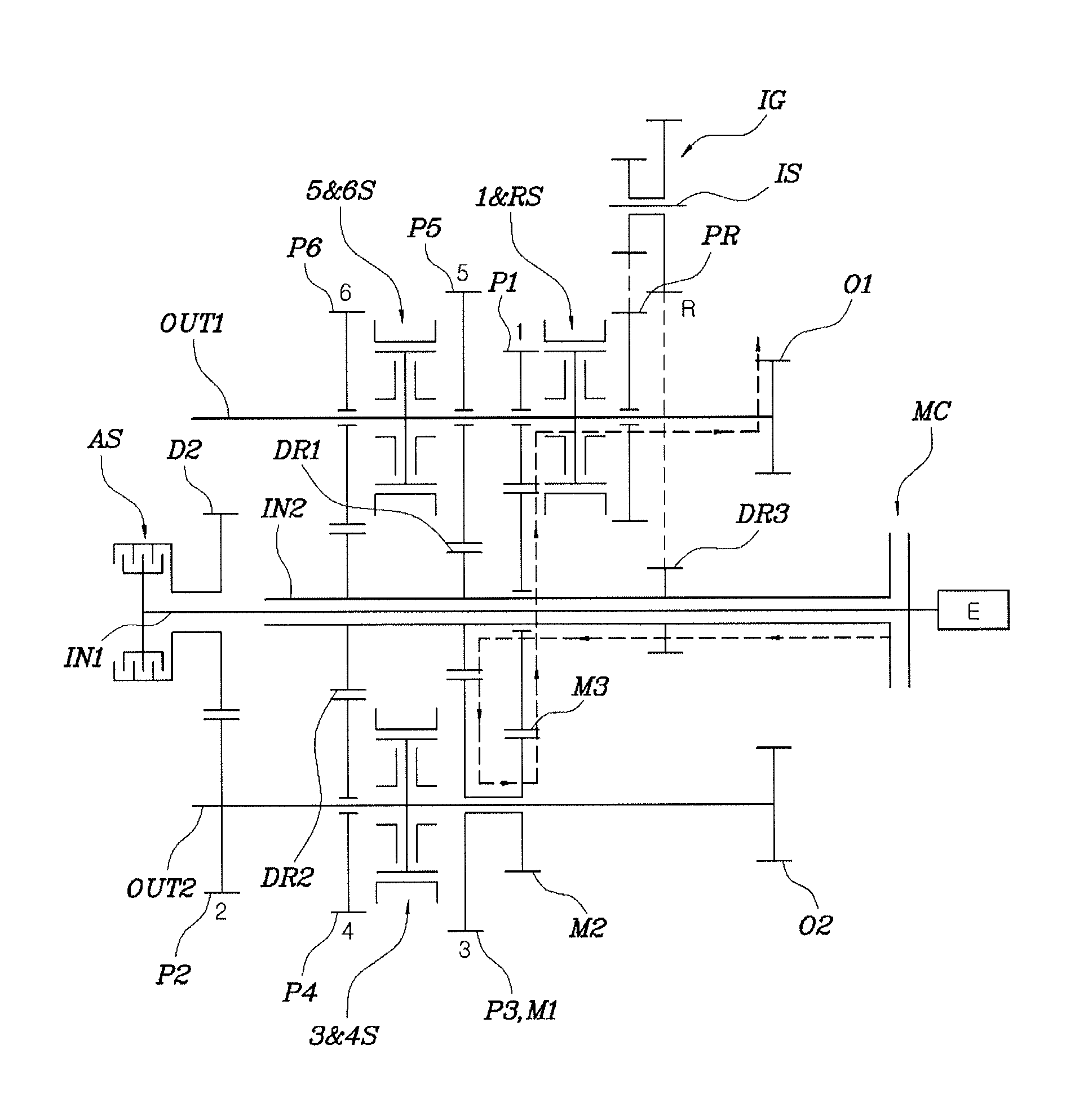
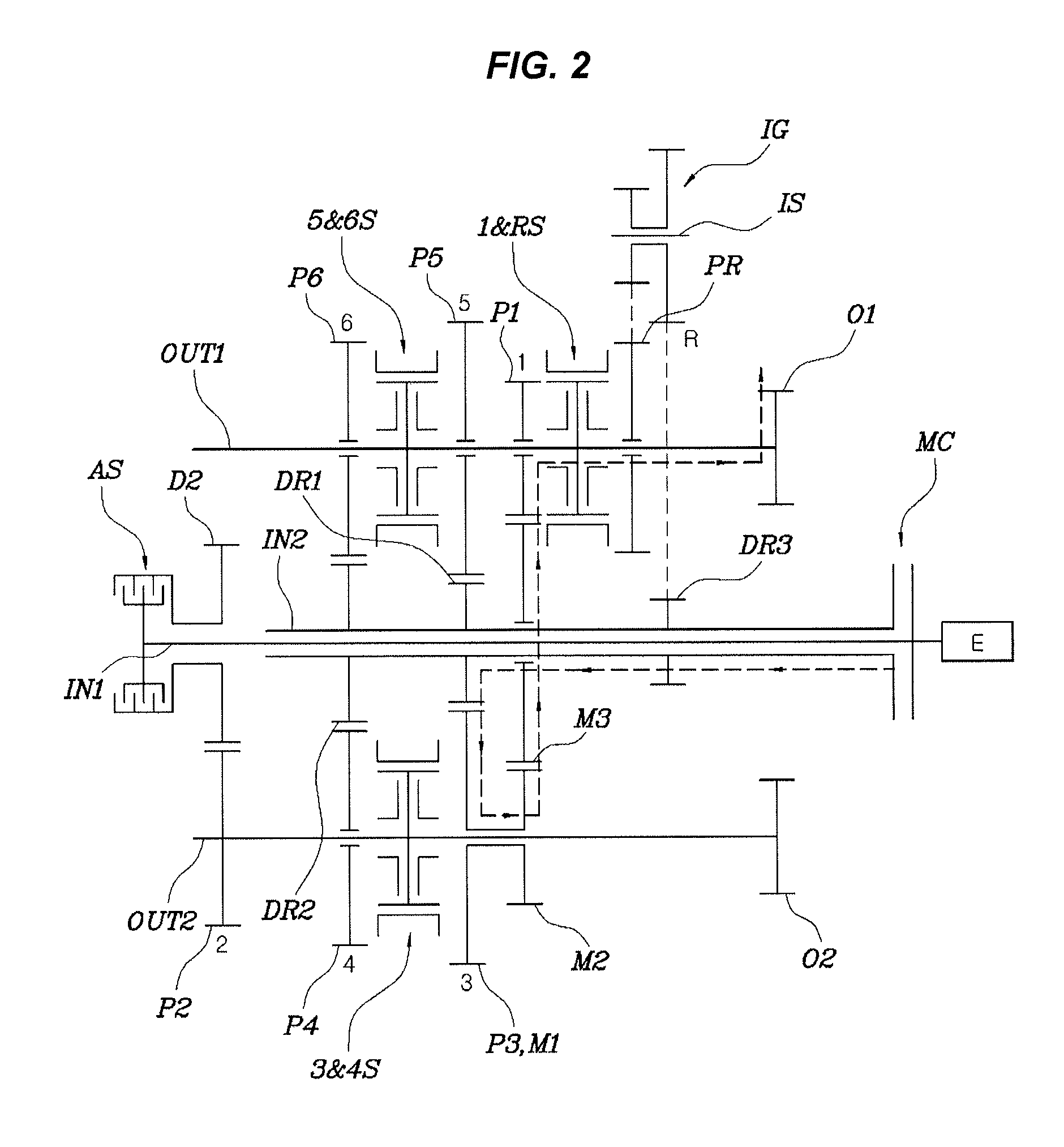
[0033]Here, the fact that the second medium gear M2 constituting the complex medium gear MG is integrally connected to the first medium gear M1 at least temporarily means that the second medium gear M2 is always integrally connected to the first medium gear M1 in the first embodiment and the second medium gear M2 may be integrally connected to or released from the first medium gear M1 by a medium synchronizing unit MS.

[0034]Meanwhile, in the first embodiment, a fifth stage driven gear P5 engaged with the first driving gear DR1 to form a fifth stage gear shift is rotatably installed on the first output shaft OUT1, a second driving gear DR2 is integrally installed on the second input shaft IN2, a fourth stage driven gear P4 engaged with the second driving gear DR2 to form a fourth stage gear shift is rotatably installed on the second output shaft OUT2, and a sixth stage driven gear P6 engaged with the second driving gear DR2 to form a sixth stage gear shift is rotatably installed on t...

second embodiment

[0043]Meanwhile, in FIG. 3, the complex medium gear MG is configured such that the first medium gear M1 and the second medium gear M2 are interrupted from or connected to each other by a medium synchronizing unit MS, and the first medium gear M1 also serves as a third stage driven gear P3 for forming a third stage gear shift together with the first driving gear DR1.

[0044]In the exemplary embodiment of the present invention, a second driving gear DR2 is installed on the second input shaft IN2, a fourth stage driven gear P4 engaged with the second driving gear DR2 to form a fourth stage gear shift is rotatably installed on the first output shaft OUT1, a fifth stage driven gear P5 engaged with the second driving gear DR2 to form a fifth gear shift is rotatably installed on the second output shaft OUT2, an R stage driven gear PR for forming a reverse gear shift is rotatably installed on the first output shaft OUT1, and a reverse idler gear IG engaged with the first driving gear DR1 and ...


PUM


Abstract

A transmission for a vehicle may include first and second input shafts, first and second output shafts, a first driving gear fixed to the second input shaft, a first medium gear engaged with the first driving gear and a second medium gear integrally connected to the first medium gear at least temporarily, and rotatably installed on the second output shaft, a third medium gear engaged with the second medium gear and rotatably installed on the second input shaft, a first stage driven gear engaged with the third medium gear and rotatably installed on the first output shaft, a second stage driving gear selectively rotatable with the first output shaft, a second stage driven gear installed on the second output shaft and engaged with the second stage driving gear, and an auxiliary clutch for selectively connecting the second stage driving gear to the first input shaft.

Description

CROSS-REFERENCE(S) TO RELATED APPLICATION[0001]The present application claims priority of Korean Patent Application Number 10-2013-0157918 filed on Dec. 18, 2013, the entire contents of which application is incorporated herein for all purposes by this reference.BACKGROUND[0002]1. Field of the Invention[0003]The present invention relates to a transmission for a vehicle, and more particularly, to a technology for a transmission structure that can overcome a torque interruption phenomenon during gear shift while utilizing a synchronized gear type transmission mechanism.[0004]2. Description of Related Art[0005]A main problem in development of transmissions mounted to vehicles is to reduce the number of parts of a transmission, the weight, overall length, and volume of the transmission.[0006]The volume of the transmission influences a mounting performance of the transmission to a vehicle, and the weight of the transmission is a factor that greatly influences a fuel ratio of the vehicle.[...

Claims


Application Information

Patent Timeline
Patent Type & Authority Patents(United States)
IPC IPC(8): F16H3/08F16H3/093
CPCF16H3/093F16H2003/0818F16H2003/0931F16H2200/0052Y10T74/19228F16H3/085F16H3/12F16H57/023F16H3/44F16H3/66
Inventor KIM, CHON OKEO, SOON KILIM, CHAE HONG
Owner HYUNDAI MOTOR CO LTD
Learn More