Industrial fabric comprising an extruded mesh and method of making thereof

a technology of extruded mesh and industrial fabric, which is applied in the direction of press section, transportation and packaging, and other domestic articles, can solve the problems of low water handling efficiency, poor elastic behavior of new fabrics, and low density, and achieve excellent elastic behavior and high through thickness compressibility and recovery. , the effect of high through thickness

Active Publication Date: 2016-05-31
ALBANY INT CORP
View PDF46 Cites 6 Cited by
  • Summary
  • Abstract
  • Description
  • Claims
  • Application Information

AI Technical Summary

Benefits of technology

[0024]One embodiment of the present invention is an ultra-resilient mesh or netting that utilizes a unique structure which provides excellent elastic behavior under a load applied normal to the surface of the mesh / net with high through thickness compressibility and recovery (resiliency). The instant structure utilizes an elastic component in at least one direction, which allows the entire structure to ‘collapse’ into itself under an applied normal load (i.e. pressure) based primarily upon the elasticity of this component and the structure geometry to conform under pressure and to “spring back” when the load (pressure) is removed, thus allowing this unique behavior.

Problems solved by technology

Eventually they must be removed due to various reasons such as lack of water handling capability, marking, or press vibration.
New fabrics also go through a break in period wherein the density is not ideal and water handling is less than optimum.
The compressibility is only due to the elastic portion (in the through thickness direction) of the yarn, and is therefore limited to such.
While larger yarns can be used, there is eventually a diminishing return on performance.
Also large yarns are heavy, and can cause objectionable sheet marking.
If the yarn is a sheath / core type, there is always the danger of delamination of the sheath from the core.
Such yarn sizes can be limited in use due to weight and potential marking considerations.
But again, using these yarns, the compressibility and spring back is limited to some portion of the yarn diameter at most.
As stated above, because of this limited resiliency, press fabrics have a relatively high void volume to handle water when new, more than is ideally required.
However as they have limited resiliency, they will continue to compact, eventually requiring removal and replacement.

Method used


Image

  • Industrial fabric comprising an extruded mesh and method of making thereof
  • Industrial fabric comprising an extruded mesh and method of making thereof
  • Industrial fabric comprising an extruded mesh and method of making thereof

Examples


Embodiment Construction

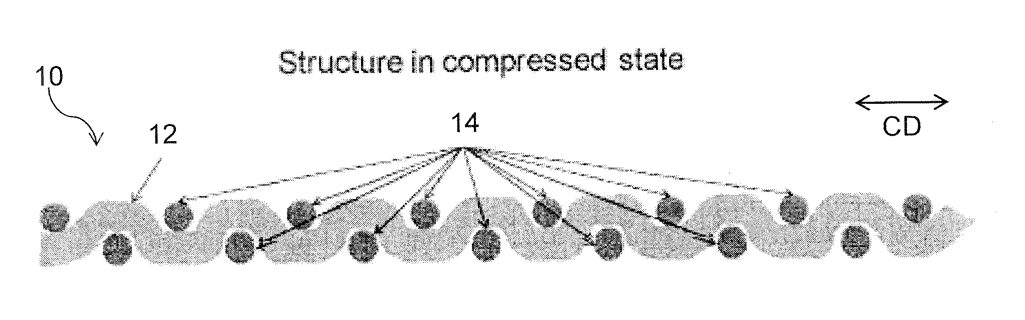
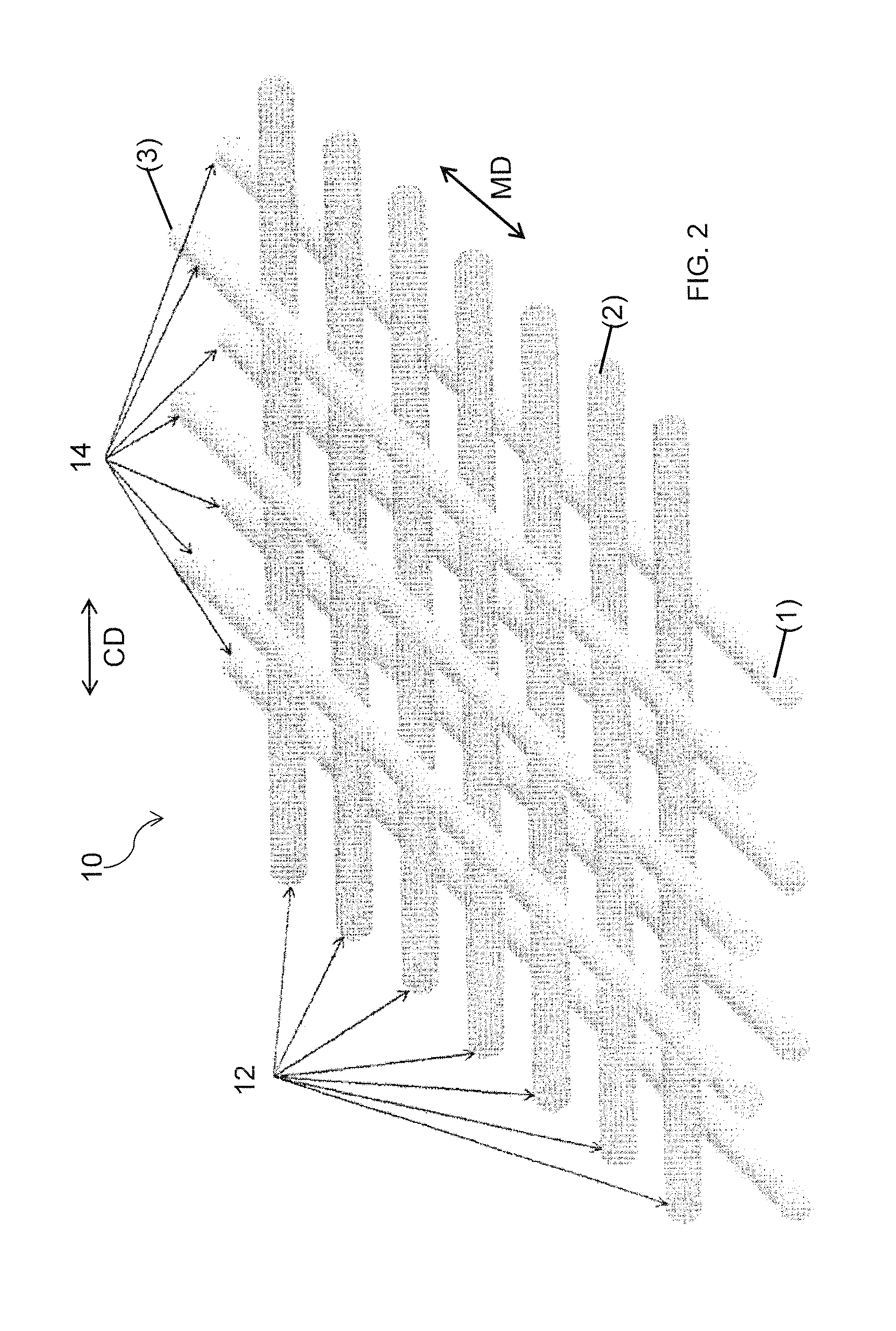
[0042]For purposes of the present invention, the terms “cross machine direction” and “transverse direction” are synonymous and sometimes simply referred to as “CD”, as are the terms “longitudinal direction” and “machine direction”, sometimes simply referred to as “MD”. However, the term “transverse” is sometimes also used to refer to strands / members / components which extend in a direction opposite to that of strands / members / components previously referred to. The meaning will be clear from the context in any particular instance.

[0043]Initially although a press fabric will be discussed, as aforesaid the present invention has application to other type fabrics or belts. With that said turning now more particularly to the figures, one embodiment of the present invention is a bicomponent extruded mesh 10 shown in FIG. 2 as having a first or bottom layer (1) comprised of functional strands 14 extruded in a parallel array oriented in the machine or running direction. A second or middle layer...


PUM

PropertyMeasurementUnit
angleaaaaaaaaaa
thicknessaaaaaaaaaa
diameteraaaaaaaaaa

Abstract

A structure for use in industrial fabrics such as paper machine clothing and engineered fabrics. The structure is a bicomponent extruded elastomeric netting or mesh having a high degree of both compressibility under an applied normal load and excellent recovery (resiliency or spring back) upon removal of that load.

Description

FIELD OF THE INVENTION[0001]The present invention relates to a structure for use in industrial fabrics such as paper machine clothing and engineered fabrics. More specifically, the structure is an extruded bicomponent elastomeric netting or mesh having both elastomeric strands or members and relatively inelastic strands, and exhibits a high degree of both compressibility under an applied normal load and excellent recovery (resiliency or spring back) upon removal of that load.BACKGROUND OF THE INVENTION[0002]An industrial fabric means an endless structure in the form of a continuous loop such as one used as a forming, press or dryer fabric (paper machine clothing or PMC) as well as a process belt such as a shoe press, calendar, or transfer belt used on a paper machine. Industrial fabrics also means fabrics used in textile finishing processes. Industrial fabrics also include other endless belts where a high degree of compressibility and resiliency is required.[0003]While the discussio...

Claims


Application Information

Patent Timeline
Patent Type & Authority Patents(United States)
IPC IPC(8): B32B5/12D21F7/08D21F3/02D21F1/00B32B5/02B29C48/05B29C48/21
CPCB32B5/12B32B5/028D21F1/0036D21F1/0063D21F3/0227D21F7/083Y10T428/24074Y10T428/24091Y10T428/24107Y10T428/24116Y10T428/24132B29C48/05B29C48/21D21F1/00B29D28/005B32B25/10B32B5/26B29L2009/00B32B5/022
Inventor HANSEN, ROBERT A.
Owner ALBANY INT CORP
Why Eureka
Try Eureka