
Modifying behavior of autonomous vehicles based on sensor blind spots and limitations

a technology of autonomous vehicles and blind spots, applied in the direction of vehicle position/course/altitude control, process and machine control, instruments, etc., can solve problems such as dangerous maneuvers

Active Publication Date: 2016-06-14
WAYMO LLC
View PDF29 Cites 41 Cited by
  • Summary
  • Abstract
  • Description
  • Claims
  • Application Information

AI Technical Summary

Problems solved by technology

Without taking into account the limitations of these sensors, this may lead to dangerous maneuvers such as passing around blind corners, moving into spaces that are partially occluded by other objects, etc.

Method used


Image

  • Modifying behavior of autonomous vehicles based on sensor blind spots and limitations
  • Modifying behavior of autonomous vehicles based on sensor blind spots and limitations
  • Modifying behavior of autonomous vehicles based on sensor blind spots and limitations

Examples


Embodiment Construction

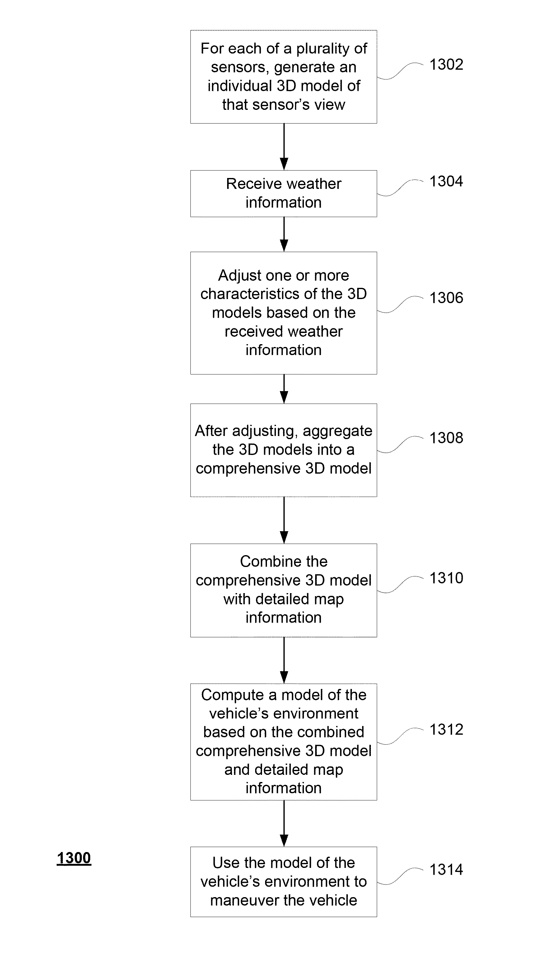
[0024]Aspects of the present disclosure relate generally to modeling a vehicle's current view of its environment. This view need not include what objects or features the vehicle is actually seeing, but rather those areas that the vehicle is able to observe using its sensors if the sensors were completely un-occluded. For example, for each of a plurality of sensors of the object detection component, a computer may generate an individual 3D model of that sensor's field of view. Weather information is received and used to adjust one or more of the models. After this adjusting, the models may be aggregated into a comprehensive 3D model. The comprehensive model may be combined with detailed map information indicating the probability of detecting objects at different locations. A model of the vehicle's environment may be computed based on the combined comprehensive 3D model and detailed map information and may be used to maneuver the vehicle.

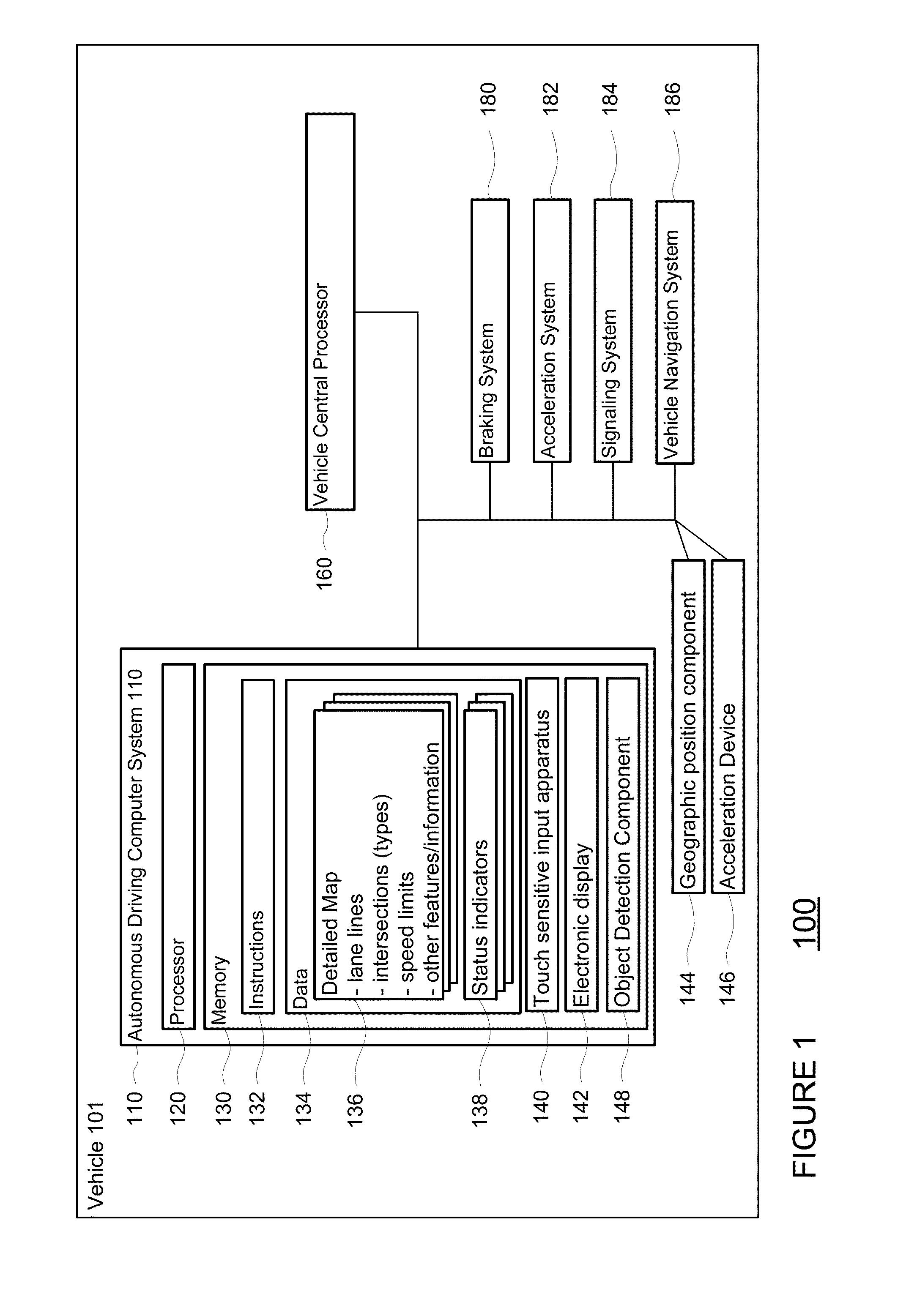
[0025]As shown in FIG. 1, an autonomous driving...


PUM


Abstract

Models can be generated of a vehicle's view of its environment and used to maneuver the vehicle. This view need not include what objects or features the vehicle is actually seeing, but rather those areas that the vehicle is able to observe using its sensors if the sensors were completely un-occluded. For example, for each of a plurality of sensors of the object detection component, a computer may generate an individual 3D model of that sensor's field of view. Weather information is received and used to adjust one or more of the models. After this adjusting, the models may be aggregated into a comprehensive 3D model. The comprehensive model may be combined with detailed map information indicating the probability of detecting objects at different locations. The model of the vehicle's environment may be computed based on the combined comprehensive 3D model and detailed map information.

Description

BACKGROUND[0001]Autonomous vehicles use various computing systems to aid in the transport of passengers from one location to another. Some autonomous vehicles may require some initial input or continuous input from an operator, such as a pilot, driver, or passenger. Other systems, for example autopilot systems, may be used only when the system has been engaged, which permits the operator to switch from a manual mode (where the operator exercises a high degree of control over the movement of the vehicle) to an autonomous mode (where the vehicle essentially drives itself) to modes that lie somewhere in between.[0002]Such vehicles are equipped with various types of sensors in order to detect objects in the surroundings. For example, autonomous vehicles may include lasers, sonar, radar, cameras, and other devices which scan and record data from the vehicle's surroundings. These devices in combination (and in some cases alone) may be used to build 3D models of the objects detected in the...

Claims


Application Information

Patent Timeline
Patent Type & Authority Patents(United States)
IPC IPC(8): G05D1/02B60W30/18B60W50/00
CPCG05D1/0248G05D1/0274G05D2201/0213B60W30/18154B60W2050/0095B60W2550/12B60W2555/20G05D1/0257G05D1/0276
Inventor DOLGOV, DMITRI A.URMSON, CHRISTOPHER PAUL
Owner WAYMO LLC
Learn More