Determination of the presence of closely spaced targets

a technology of closely spaced targets and observable objects, applied in the direction of instruments, communication jamming, measurement devices, etc., can solve the problems of no way to know which type of objects is observed, and no means

Inactive Publication Date: 2007-05-22
LOCKHEED MARTIN CORP
View PDF15 Cites 17 Cited by
  • Summary
  • Abstract
  • Description
  • Claims
  • Application Information

AI Technical Summary

Benefits of technology

[0015]A method according to an aspect of the invention is for detection of remote targets. The method comprises the step of receiving from a remote target a plurality of signals, which may be either (one of) reflected

Problems solved by technology

However, there is no way to know which type is observed, and no means, other than multiple observa

Method used


Image

  • Determination of the presence of closely spaced targets
  • Determination of the presence of closely spaced targets
  • Determination of the presence of closely spaced targets

Examples


Embodiment Construction

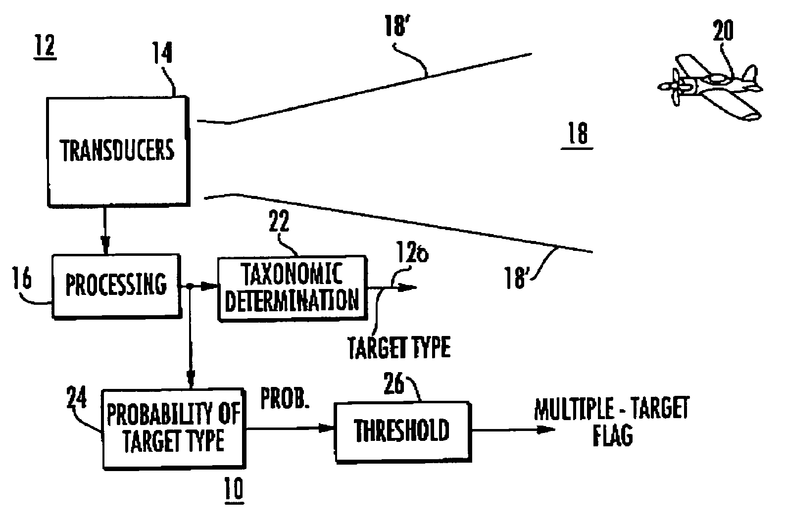
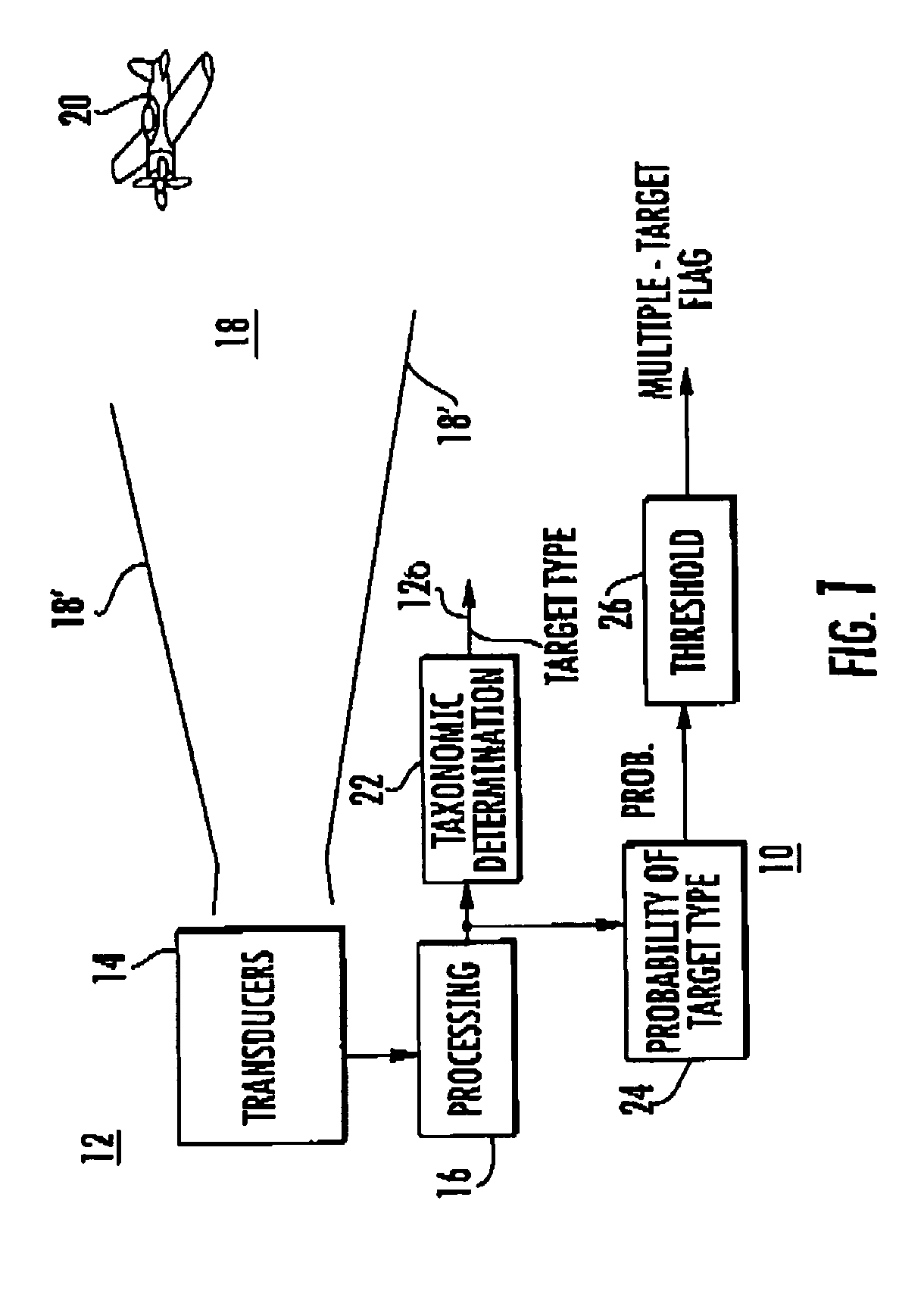
[0024]In FIG. 1, probability-of-target-type block 24 represents a portion of the function of multiple target presence detection or determination. Such multiple targets may arise under those circumstances in which one aircraft or vehicle shadows another, flying so closely behind that the two targets lie within the same range bin of the sensor. It can be important to detect such multiple targets, especially in a military or antiterror context. The remaining portion of the function of multiple target presence detection is performed by a thresholding block 26.

[0025]In general, the processing performed in block 24 of FIG. 1 uses the same information from the sensor or transducer that is currently used to make the taxonomic determination in block 22. More particularly, a determination is made of the prior probability that more than one target or object is observed by noting the number of occurrences of evidence of a particular type of target out of a particular number of observations.

[002...


PUM


Abstract

An active or passive sensor observes a region, and generates evidence of the type of target or object viewed. The evidence is processed to determine the prior probability that the object is of a particular type. The prior probability so determined is thresholded to produce an indication of the presence of multiple targets or objects in a range bin, suggestive of shadowing of a target.

Description

FIELD OF THE INVENTION[0001]This invention relates to the determination of the presence of two or more closely spaced or “tag-along” targets observed by a sensor or sensor suite.BACKGROUND OF THE INVENTION[0002]Fusion of digital information is used in areas such as battlefield monitoring and control operations. A battlefield may be observed by a large number of various types of sensors, each of which more-or-less continuously monitors its “field of view” to produce digital information which is evidence of the nature or characteristics of the object or objects within the field of view. If the platform on which the sensor is mounted is moving, the field of view may change with time. Such sensors receive raw data from an observed direction or space in either a passive or an active manner, and process the information according to some algorithm in order to make a determination of the nature of the object or condition. For example, a radar system operating as an active sensor may transmi...

Claims


Application Information

Patent Timeline
IPC IPC(8): G01S13/66
CPCG01S7/41G01S13/66
Inventor FRIESEL, MARK A.
Owner LOCKHEED MARTIN CORP
Why Eureka
Try Eureka