
Object detection in images

a technology for objects and images, applied in image enhancement, image analysis, instruments, etc., can solve problems such as failure of above-color constancy discriminators, mckenna et al. presenting problems, and inability to fill in by reference to rgb subtraction masks

Active Publication Date: 2010-06-22
BRITISH TELECOMM PLC
View PDF2 Cites 34 Cited by
  • Summary
  • Abstract
  • Description
  • Claims
  • Application Information

AI Technical Summary

Benefits of technology

The present invention provides an improved method for detecting objects in an image by segmenting picture elements representing foreground and background objects using a foreground segmentation technique and a shadow processing technique. The method compensates for any holes or bisections in the segmented picture elements caused by the shadow processing. The method also includes steps of repeatedly segmenting as foreground surrounding picture elements until all foreground objects are segmented. The invention ensures that any shadows or highlights in the image do not affect the object detection. The computer program and system for detecting objects in an image are also provided.

Problems solved by technology

One of the problems known in the art relating to the automated detection of objects is of how to compensate for changes in lighting conditions, and in particular of how to discern between an actual object, and a shadow or highlight that that object may cast or otherwise contain.
However, McKenna et al. also note that the above colour constancy discriminator fails when a foreground object is the same chromaticity as the background e.g. when black trousers cross a grey footpath.
Whilst the colour constancy and gradient techniques described by McKenna et al. are effective at identifying shadows for the purposes of a foreground-background pixel segmentation, the technique described by McKenna et al presents some problems when used in real situations due to the connected component analysis being performed before taking into account the “holes” due to the segmentation.
As a consequence, overlapping “holes” will not be recognised as such, and hence cannot be filled in by reference to the RGB subtraction mask.

Method used


Image

  • Object detection in images
  • Object detection in images
  • Object detection in images

Examples


Embodiment Construction

[0043]An exemplary embodiment of the present invention will now be described with respect to the figures, and an example of the operation of the embodiment given.

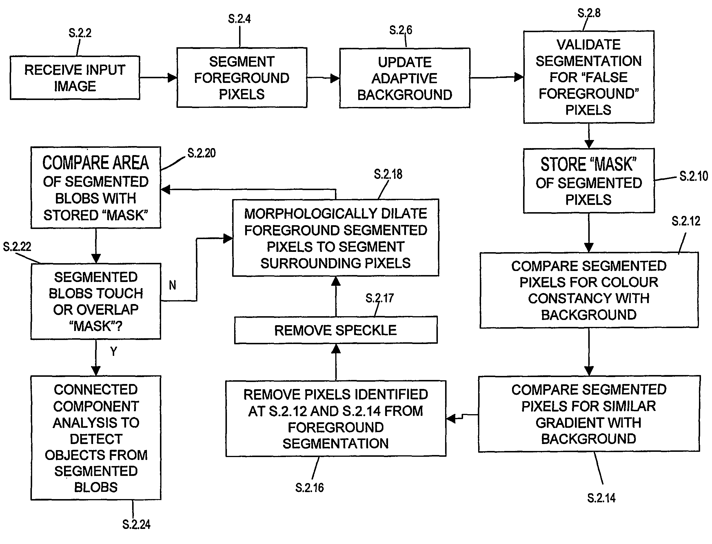
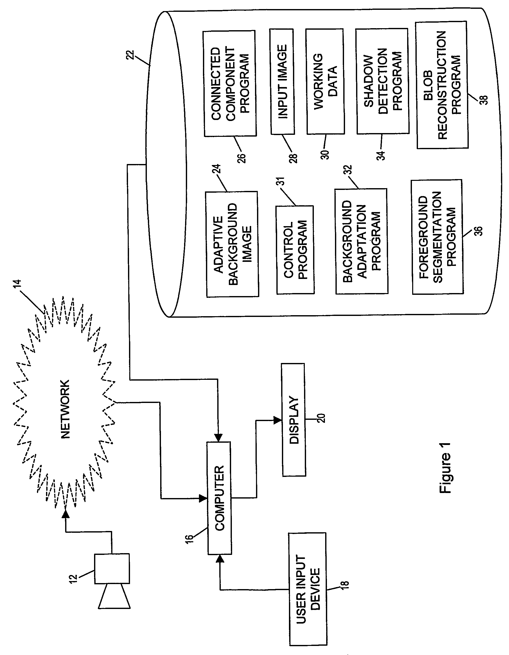
[0044]FIG. 1 illustrates an example system architecture which provides the embodiment of the invention. More particularly, as the present invention generally relates to an image processing technique for detecting objects within input images, the invention is primarily embodied as software to be run on a computer. Therefore, the system architecture of the present invention comprises a general purpose computer 16, as is well known in the art. The computer 16 is provided with a display 20 on which output images generated by the computer may be displayed to a user, and is further provided with various user input devices 18, such as keyboards, mice, or the like. The general purpose computer 16 is also provided with a data storage medium 22 such as a hard disk, memory, optical disk, or the like, upon which is stored programs and ...


PUM


Abstract

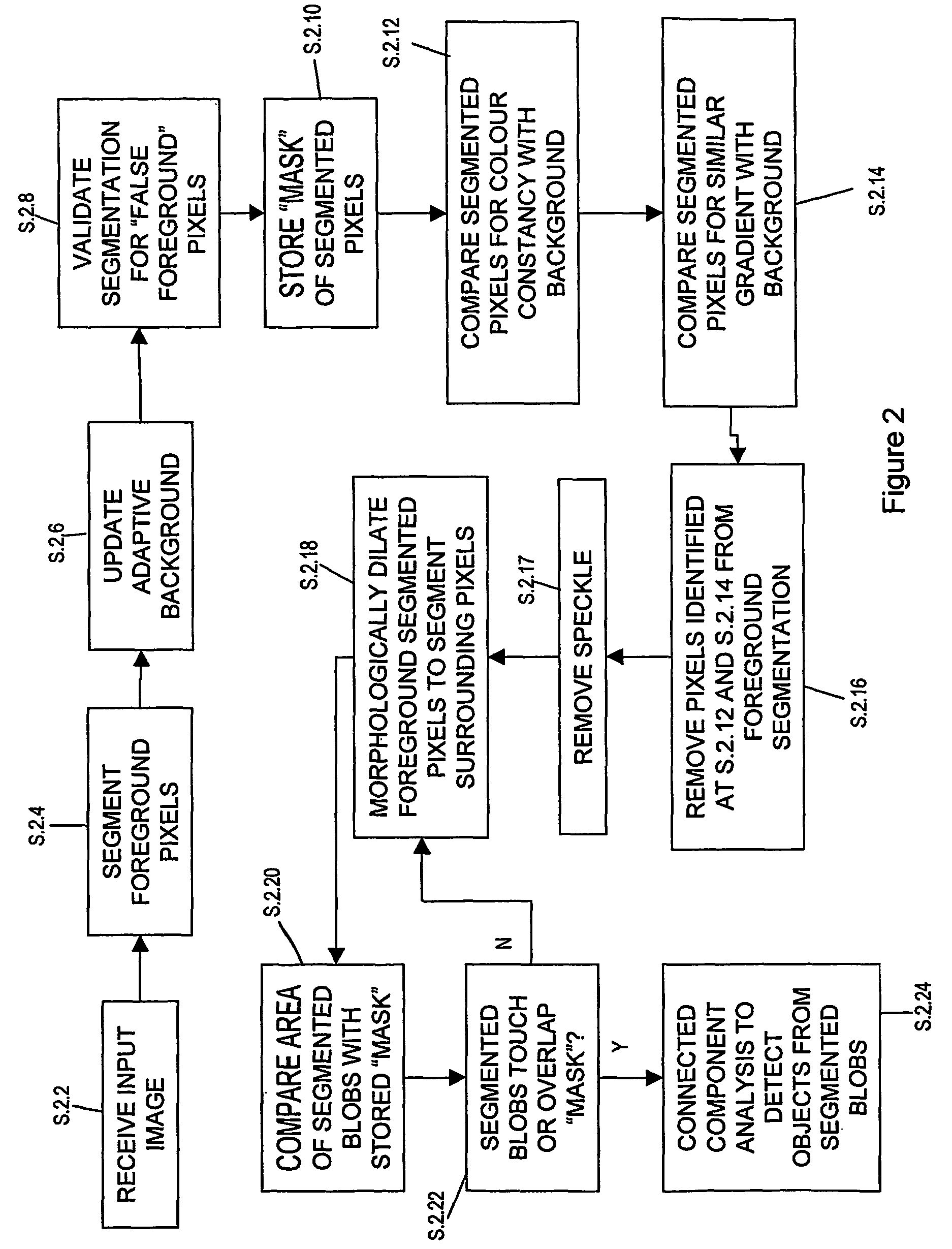
A segmentation operation is applied to an input image to identify foreground objects of interest, and then a shadow removal operation is applied to remove any detected shadows from the foreground segmentation. The shadow removal algorithms can leave holes and bisections in the segmentation map, however, which will then subsequently impact on an object detection step performed using connected component analysis. To get around this problem, a conditional morphological dilation operation is applied to the segmentation map to ‘grow’ the segmented blobs to fill in any holes and bisections, without re-growing shadow pixels in the segmentation. The result is an object detection method and system which is robust to illumination changes causing shadows and / or highlights.

Description

[0001]This application is the US national phase of international application PCT / GB2004 / 004685 filed 8 Nov. 2004 which designated the U.S. and claims benefit of GB 0326374.6, dated 12 Nov. 2003, the entire content of which is hereby incorporated by reference.BACKGROUND[0002]1. Technical Field[0003]The present invention relates to a method and system for detecting objects in images, and particularly, but not exclusively, to a method and system which detects moving objects taking into account lighting shadows and highlights of those objects.[0004]2. Related Art[0005]The automatic detection of moving objects such as people or vehicles within video images of a scene has been a goal of many researchers, and is a precursor to the provision of automated classification or tracking applications. Additionally, automated object detection systems are in themselves of use for monitoring and detection applications. The actual step of discriminating between picture elements (pixels) within an imag...

Claims


Application Information

Patent Timeline
Patent Type & Authority Patents(United States)
IPC IPC(8): G06K9/42G06K9/44G06K9/40G06K9/34G06T5/00G06T5/30G06V10/28
CPCG06K9/344G06K9/346G06K9/38G06T7/0081G06T2207/30236G06T2207/10016G06T2207/20036G06T2207/20144G06T7/11G06T7/194G06V10/273G06V30/153G06V10/28
Inventor XU, LI-QUNLANDABASO, JOSE-LUIS
Owner BRITISH TELECOMM PLC
Learn More