Dc-dc converter

a converter and dc technology, applied in the direction of electric variable regulation, process and machine control, instruments, etc., can solve the problems of control system instability, upward and downward fluctuation of output voltage vo, and the response characteristic of the operational amplifier oamp cannot keep up with sharp load changes, etc., to achieve enhanced load response characteristics and high efficiency

Inactive Publication Date: 2012-06-07
SANKEN ELECTRIC CO LTD
View PDF5 Cites 9 Cited by
  • Summary
  • Abstract
  • Description
  • Claims
  • Application Information

AI Technical Summary

Benefits of technology

[0018]An object of the present invention is to provide a low-noise and highly efficient DC-DC converter which hardly causes ON / OFF ratios to change despite load fluctuation and thus has an enhanced load response characteristic.

Problems solved by technology

In this respect, the response characteristic of the operational amplifier OAMP cannot keep up with sharp load changes between the heavy and light loads.
This causes a problem of upward and downward fluctuation in the output voltage Vo.
In addition, making a transient response of the operational amplifier OAMP faster leads to reducing a phase margin of a feedback system for the entire DC-DC converter, and poses a problem that the control system becomes unstable.

Method used


Image

  • Dc-dc converter
  • Dc-dc converter
  • Dc-dc converter

Examples


embodiment 1

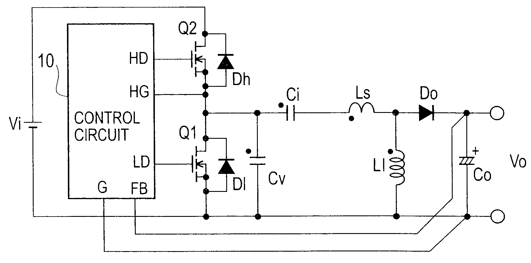
[0038]FIG. 9 is a circuit diagram showing a DC-DC converter of Embodiment 1 of the present invention. In FIG. 9, a series circuit (a first series circuit), which includes a switching element Q1 (a first switching element) formed of a MOSFET and the like as well as a switching element Q2 (a second switching element) formed of a MOSFET and the like, is connected to both ends of a direct-current power source Vi.

[0039]A voltage resonant capacitor Cv, as well as a series circuit (a second series circuit) including a current resonant capacitor Ci, a reactor Ls and a reactor Ll, is connected to both ends of the switching element Q1. A series circuit including a diode Do and a smoothing capacitor Co is connected to both ends of the reactor Ll. The diode Do and the smoothing capacitor Co constitute a half-wave rectifying / smoothing circuit.

[0040]The cathode of the diode Do and the positive electrode of the smoothing capacitor Co are connected to a FB terminal of a control circuit 10. The nega...

embodiment 2

[0068]FIG. 13 is a circuit configuration diagram showing a DC-DC converter of Embodiment 2 of the present invention. The DC-DC converter of Embodiment 2 shown in FIG. 13 is different from the DC-DC converter of Embodiment 1 shown in FIG. 9 in the following points. The cathode of a diode Do is connected to a connection point between a reactor Ls and a reactor Ll. The anode of the diode Do, the negative electrode of a smoothing capacitor Co, one end of a resistor Ra are connected to the positive electrode of an output voltage terminal Vo. The positive electrode of the smoothing capacitor Co is connected to the negative electrode of the output voltage terminal Vo, the negative electrode of a direct-current power source Vi, the ground G of a control circuit 11. The other end of the resistor Ra is connected to a FB terminal of the control circuit 11.

[0069]FIG. 14 shows the configuration of the control circuit 11. The control circuit 11 includes a variable frequency oscillator VCO, a one-...


PUM


Abstract

The present invention provides a DC-DC converter including: a first series circuit which is connected to the two ends of a direct-current power source Vi, and in which a first switching element Q1 and a second switching element Q2 are connected together in series; a control circuit 10 configured to alternately turn on and off the first switching element and the second switching element; a second series circuit which is connected to the two ends of the first switching element, and in which a first capacitor Ci, a first reactor Ls and a second reactor Ll having a larger value than the first reactor are connected together in series; and rectifying/smoothing circuits (Do, Co) configured to rectify and smooth a voltage between the two ends of the second reactor, and to output a direct-current output voltage.

Description

TECHNICAL FIELD[0001]The present invention relates to a DC-DC converter which is excellent in load transient response.BACKGROUND ART[0002]FIG. 1 shows an example of a conventional DC-DC converter.[0003]In FIG. 1, a series circuit, which includes a switching element Q1 formed of a MOSFET and the like as well as a switching element Q2 formed of a MOSFET and the like, is connected to a direct-current power source Vi. In addition, a series circuit including a reactor L and a smoothing capacitor Co is connected in parallel to the switching element Q1 at its two ends. A control circuit 10a alternately turns on and off the switching element Q1 and the switching element Q2, whereby an output voltage Vo is obtained from the two ends of the smoothing capacitor Co.[0004]In other words, the DC-DC converter is formed of a general step-down chopper circuit including the switching element Q2, the reactor L, a parasitic diode of the switching element Q1, and the smoothing capacitor Co. The DC-DC co...

Claims


Application Information

Patent Timeline
Patent Type & Authority Applications(United States)
IPC IPC(8): G05F1/46
CPCH02M3/155H02M3/1588Y02B70/16Y02B70/1466H02M2001/0032Y02B70/10H02M1/0032
Inventor USUI, HIROSHI
Owner SANKEN ELECTRIC CO LTD
Why Eureka
Try Eureka