Drive system with a drive chain guided over a sprocket

Active Publication Date: 2017-04-25
SIMERTIS
View PDF16 Cites 0 Cited by
  • Summary
  • Abstract
  • Description
  • Claims
  • Application Information

AI Technical Summary

Benefits of technology

[0013]The embodiment of the drive chain according to the present invention in addition makes possible a chain str

Problems solved by technology

With these types of drive systems, however, the problem occurs that with increasing operation, a wear-related lengthening of the drive chain with an increase of its spacing occurs.
With this type of drive system, eventu

Method used


Image

  • Drive system with a drive chain guided over a sprocket
  • Drive system with a drive chain guided over a sprocket
  • Drive system with a drive chain guided over a sprocket

Examples


Example

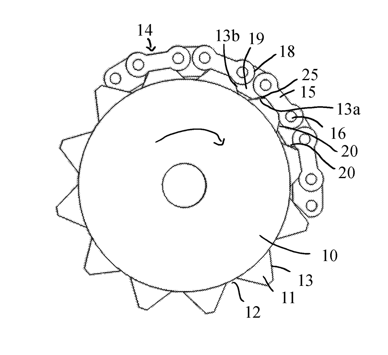
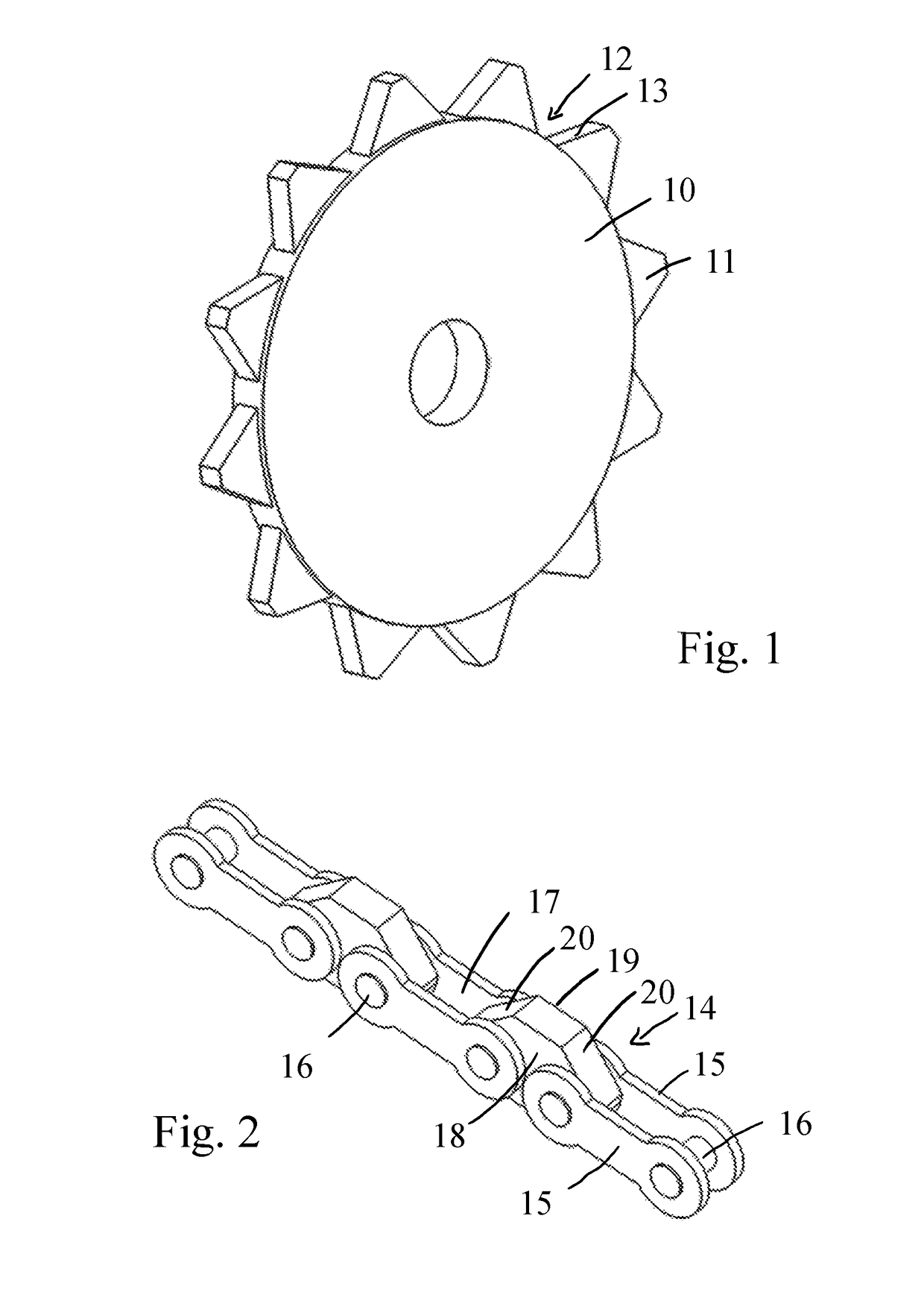
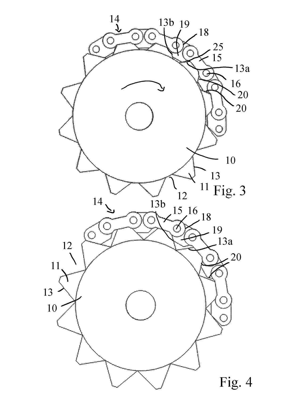
[0022]The sprocket 10 shown in FIG. 2 has teeth 11 distributed on its outer circumference with tooth intermediate spaces 12 formed therebetween. The teeth 11 have an angled shape with linearly running tooth flanks 13, whereby the outer tooth tips are flat.

[0023]As shown in FIG. 2, the individual chain links 14 comprise a drive chain made of, respectively, two link plates 15 arranged parallel to one another, which are connected to one another at their ends by means of a respective chain bolt 16 engaging through an associated opening. In contrast to the state of the art, in the series of chain links 14, no inner plates and outer plates are provided; in addition, the respective link plates 15 lie in a plane, because the individual chain links 14 are connected to one another not directly, rather via connecting plates 18 interconnected therebetween, which are engaged through at both of their ends by one of the chain bolts 16 associated with the chain links 14 connected to the respective ...


PUM


Abstract

A drive system with a drive chain which is guided over a sprocket (10), said sprocket having a sequence of teeth (11) arranged on its circumference, and which is composed of a succession of chain links (14), wherein each chain link (14) is composed of at least two link plates (15) which are arranged parallel to one another and which are connected to one another by means of link pins (16), is characterized in that the individual chain links (14) are coupled to one another by means of at least one connecting plate (18) which is arranged between said chain links and which permits a parallel displacement of the chain links (14) relative to one another, wherein each connecting plate (18) has at least one projection (19), and projections (19) and teeth (11) have in each case an angular form with rectilinearly running tooth flanks (13) and engagement flanks (20), and in that, in the case of a load-induced elongation of the connecting plates (18), the engagement flanks (20), starting with the final connecting plate (18) which is in engagement as far as the first connecting plate (18) which is passing into engagement, slide outward on the tooth flanks (13) of the individual successive teeth (11) such that the areal contact is maintained.

Description

[0001]The instant application should be granted the priority dates of Jul. 6, 2012, the filing date of the corresponding German patent application 10 201 2 106068.1, as well as Jul. 5, 2013, the filing date of the international patent application PCT / EP2013 / 064244.BACKGROUND OF THE INVENTION[0002]The invention relates to a drive system with a drive chain guided over a sprocket, the sprocket having a sequence of teeth arranged on its circumference and which is composed of a succession of chain links, wherein each chain link is composed of at least two link plates that are arranged parallel to one another and connected to one another by means of link pins that engage through associate openings and the teeth of the sprocket engage in the intermediate spaces existing between the link plates and defined by the link pins.[0003]A drive chain formed for such a drive system in cooperation with a sprocket as a plate link chain is known from DE 42 33 552 A1. In this connection, the individual ...

Claims


Application Information

Patent Timeline
IPC IPC(8): F16G13/04
CPCF16G13/04
Inventor DIETRICH, MICHAELHAUT, HOLGER
Owner SIMERTIS
Why Eureka
Try Eureka