Multiple-antenna jamming system

a jamming system and multi-antenna technology, applied in direction controllers, instruments, using reradiation, etc., can solve the problems of enemy radar being incapable of accurately tracking the missile, initiating the destruction of the missile, and presenting a potential threat to the effective lethality of anti-armor missiles, etc., to achieve the effect of maximizing the effectiveness of the jamming system

Inactive Publication Date: 2005-08-23
ARMY UNITED STATES OF AMERIA AS REPRESENTED BY THE SEC OF THE
View PDF6 Cites 37 Cited by
  • Summary
  • Abstract
  • Description
  • Claims
  • Application Information

AI Technical Summary

Benefits of technology

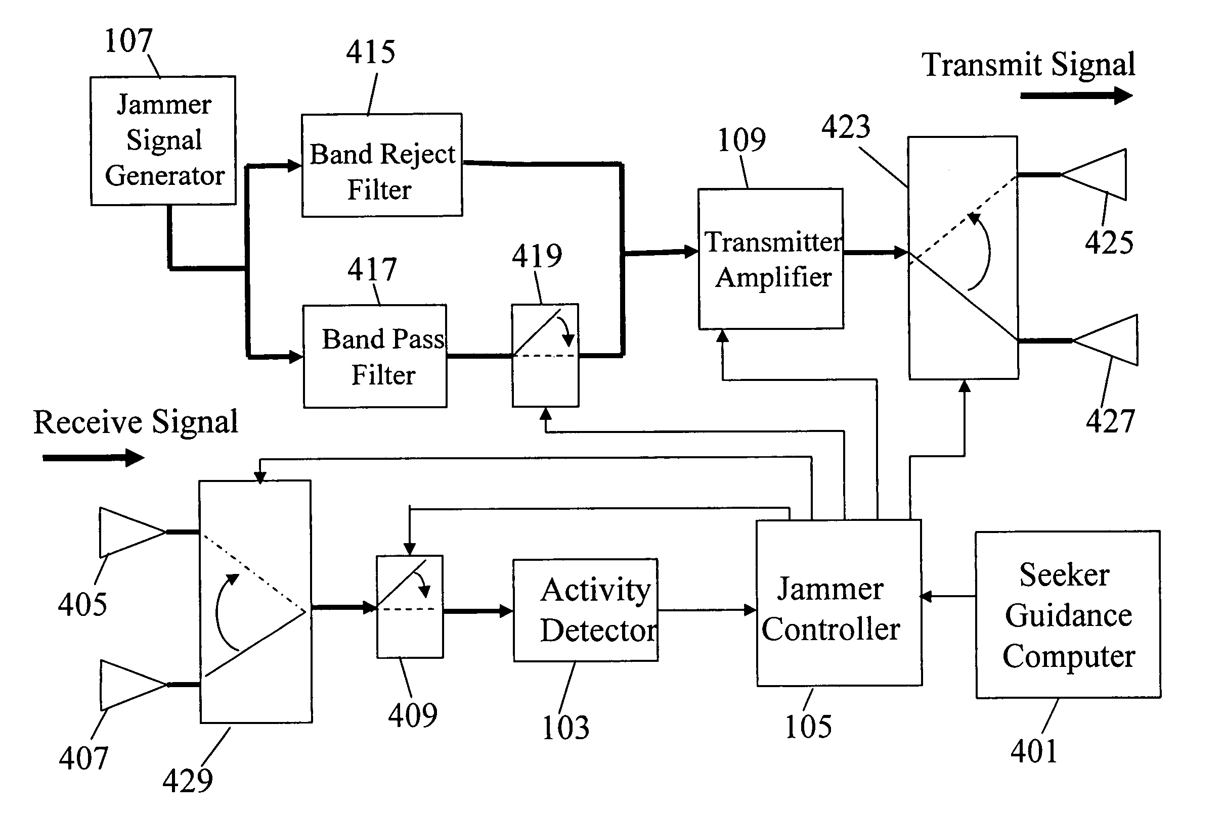
[0008]The Multiple-Antenna Jamming System (MAJS) solves the above-described problems and many others by utilizing more than one each receiving antenna and transmitting antenna, and incorporating a means for synchronizing the emission sequence of the jammer with the emission sequence of the seeker so that any jamming signals that are in the in-seeker-band are not emitted simultaneously with the seeker signals. The Jamming System uses information relative to the missile's line-of-sight to the target and the associated enemy radar to select and use the receiving and transmitting antennas that are most advantageously positioned to maximize the effectiveness of the Jamming System.

Problems solved by technology

Therefore, APS present a potential threat to the effective lethality of anti-armor missiles.
The jamming signal is intended to interfere with the enemy radar's reception of its own signal being reflected from the surface of the incoming missile.
With successful interference, the enemy radar is rendered incapable of accurately tracking the missile and initiating the destruction of the missile before it can strike the target vehicle.
The jamming process, however, presents several problems when the seeker employed by the missile is an active radio-frequency (RF) seeker.
The problems are particularly acute when the frequencies of the jamming signals are very close to the operating band of the RF seeker itself.
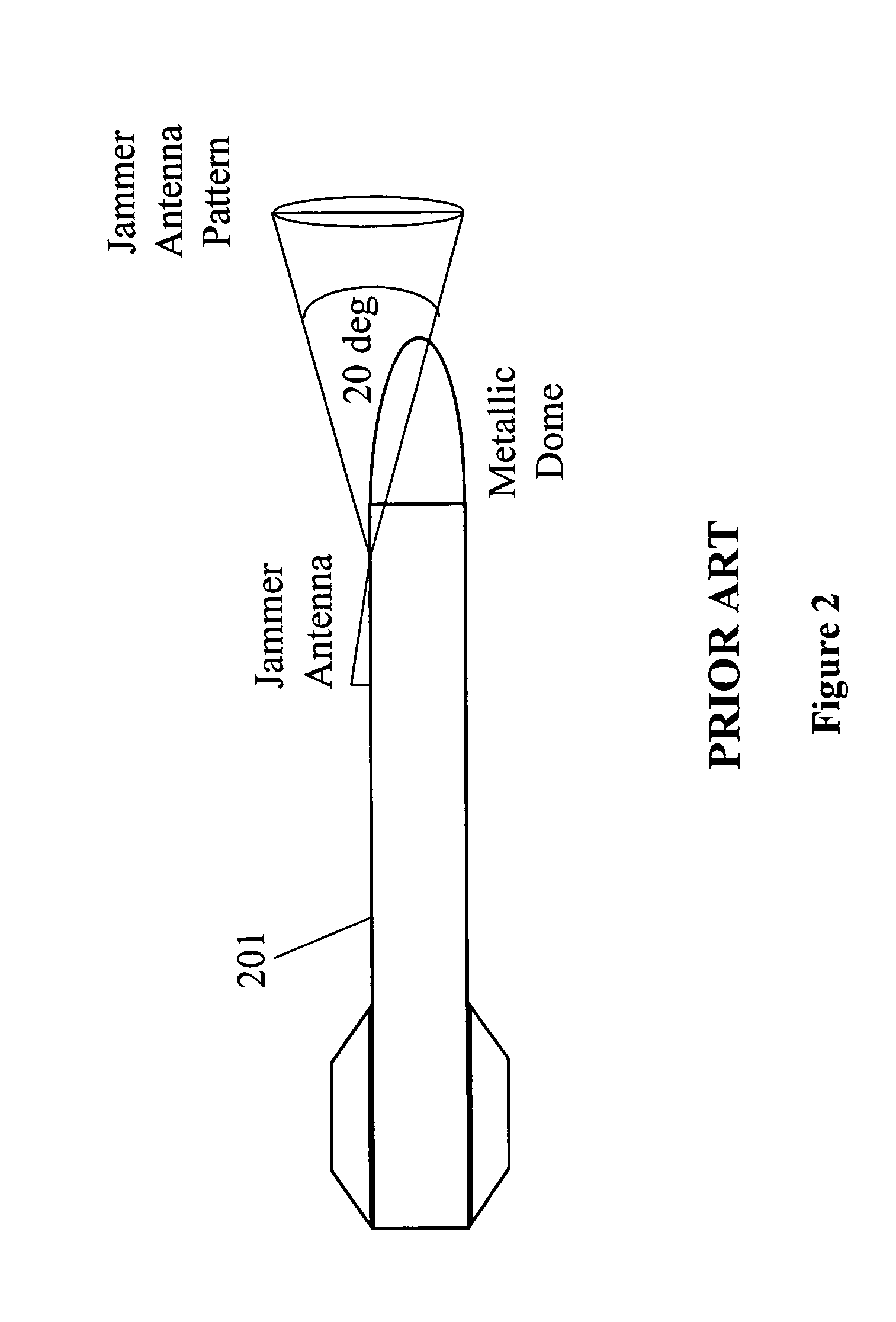
One problem is that the conformal antennas do not function well on a missile that has a transmissive radome in front of the seeker to protect the seeker hardware.
However, when a transmissive radome covers the seeker at the front-end of missile 201, the radome, not being electrically conductive, does not support the wave propagation to the other side of the missile.
Antenna pattern shadowing is a significant problem because the angle between the missile body and the line of sight to the target may be up to + / −20 degrees due to the flight trajectory of the missile.
This means that if the required jamming spatial angle is greater than the coverage angle of the transmitting antenna, the likelihood of successful jamming of the enemy radar is very low, with a corresponding increase in the likelihood of successful tracking of the missile by the enemy radar.
Another significant problem occurs when the jamming signals interfere with the seeker signals.
Such confusion and unintentional jamming can occur if the enemy radar, jammer and the missile seeker all emit signals in the same or close frequency band.
The false signals may set off the detector and jammer in the missile to no useful purpose.
Further, the transmit pulse from the seeker can cause power-handling difficulties for the jammer since they have the potential to overdrive the activity detector.
Yet a third problem occurs when the jammer energy enters the seeker receiver through the seeker antenna backlobes and raises the interference level to such that the seeker receiver's minimum detectable signal required for function is increased.
Such desensitization of the seeker receiver greatly decreases the seeker effectiveness with corresponding reduction in the target detection range and tracking accuracy.

Method used


Image

  • Multiple-antenna jamming system
  • Multiple-antenna jamming system
  • Multiple-antenna jamming system

Examples


Embodiment Construction

[0015]Referring now to the drawing wherein like numbers represent like parts in each of the several figures and dark arrows indicate RF signal travel while light arrows indicate electronic command signals, the structure and function of the multiple-antenna jamming system (MAJS) are explained in detail. The MAJS system resides in a frequency seeker missile 201 and is located typically between the warhead and seeker portions of the missile. The MAJS utilizes seeker guidance computer 401 that already is a part of the seeker.

[0016]During the missile's flight toward the selected target, the guidance computer controls the pattern of the seeker pulses emitted toward the target, setting the frequency band of the emitted pulses and determining the duration of the listening period between two consecutive emitted pulses, and also generates information relative to the missile's line-of-sight to the target. Any active protection system (APS) that protects the target also emits pulses to detect a...


PUM


Abstract

The Multiple-Antenna Jamming System (MAJS) is useful for missile-borne jamming of active protection system radars that operate in close proximity to the frequency band of the missile's radio frequency seeker. The MAJS utilizes multiple receiving and transmitting antennas to reduce shadowing effects due to the transmissive radome. It also channelizes the jamming signals into in-seeker-band and out-of-seeker band signals to synchronize the transmission of jamming signals with the emit-listen pattern of the missile seeker and to eliminate the problem of de-sensitizing the RF seeker from the jammer energy. The in-seeker-band jamming signals are transmitted only concurrently with the missile seeker emissions and any signals emanating from an enemy radar are received only during the listen mode of the missile seeker.

Description

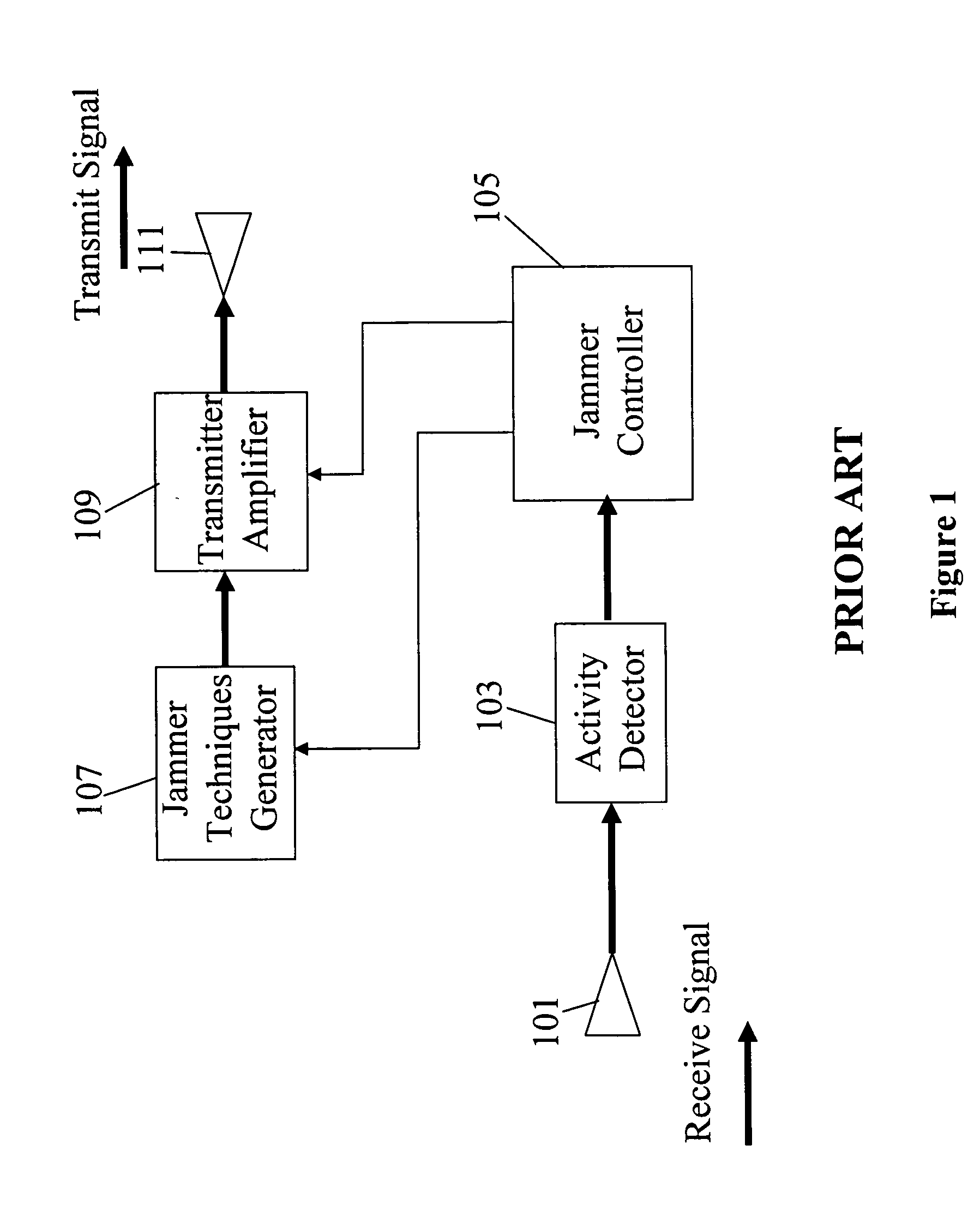
DEDICATORY CLAUSE[0001]The invention described herein may be manufactured, used and licensed by or for the Government for governmental purposes without the payment to us of any royalties thereon.BACKGROUND OF THE INVENTION[0002]Active Protection Systems (APS) are small air defense systems that provide protection for ground vehicles such as tanks against anti-tank guided missiles (ATGMs) and rocket propelled grenades (RPGs). Therefore, APS present a potential threat to the effective lethality of anti-armor missiles. To counteract the APS, missile-borne counter-active protection system (CAPS) jammers have been developed. The aim of such jammers is to disable the APS fire control radar so that the targeted ground vehicle remains vulnerable to the missile attack. A representative architecture of a CAPS jammer is depicted in FIG. 1. In a typical operation mode, any emissions from APS enemy radar are monitored by receiving antenna 101 in conjunction with activity detector 103. When such e...

Claims


Application Information

Patent Timeline
Patent Type & Authority Patents(United States)
IPC IPC(8): F42B15/00F42B15/01G01S7/38H04K3/00
CPCG01S7/38
Inventor HALLADAY, RALPH H.CHRISTIAN, MICHAEL R.LOVELACE, DONALD E.
Owner ARMY UNITED STATES OF AMERIA AS REPRESENTED BY THE SEC OF THE
Why Eureka
Try Eureka