Fluidic actuation for improved diffuser performance

a technology of fluidic actuation and diffuser, which is applied in the direction of wind motors with parallel air flow, wind motors with perpendicular air flow, combustion air/fuel air treatment, etc. it can solve the problem of limiting the maximum amount of work that can be extracted, limiting the performance of steam turbine exhaust systems, and limiting the exhaust pressure recovery coefficient to a value of 0.25-0.3

Inactive Publication Date: 2005-05-24
GENERAL ELECTRIC CO
View PDF36 Cites 66 Cited by
  • Summary
  • Abstract
  • Description
  • Claims
  • Application Information

AI Technical Summary

Benefits of technology

[0013]In another embodiment, a method of improving diffuser performance includes allowing a main flow to pass through the diffuser, providing an opening in a diffuser wall, selecting a fluid source, injecting fluid into the opening for preventing separation of the main flow from the diffuser wall, and directing the fluid at an angle relative to the main flow and relative to the diffuser wall which will maximize effectiveness.

Problems solved by technology

For turbine exhaust systems, any constraint on the exhaust diffuser area ratio imposes a limitation on maximum amount of work that can be extracted by the turbine.
Similarly, the performance of a steam turbine exhaust system is limited by geometry constraints and flow separation issues.
This issue, in addition to constraints on the length of the diffuser, limits the exhaust pressure recovery coefficient to a value of 0.25-0.3.
Splitter vanes have the disadvantage of increasing skin friction (and therefore losses) and appear to work relatively well only for uniform inlet flows.
Inlet swirl, for instance, can substantially deteriorate the performance.
In principle, they are expected to fail to yield a substantial increase in diffuser performance if, as it is the case downstream of the last turbine stage at the diffuser inlet, the diffuser inlet flow profile is severely skewed and characterized by large regions of low momentum fluid in the vicinity of the separation point.

Method used


Image

  • Fluidic actuation for improved diffuser performance
  • Fluidic actuation for improved diffuser performance
  • Fluidic actuation for improved diffuser performance

Examples


Embodiment Construction

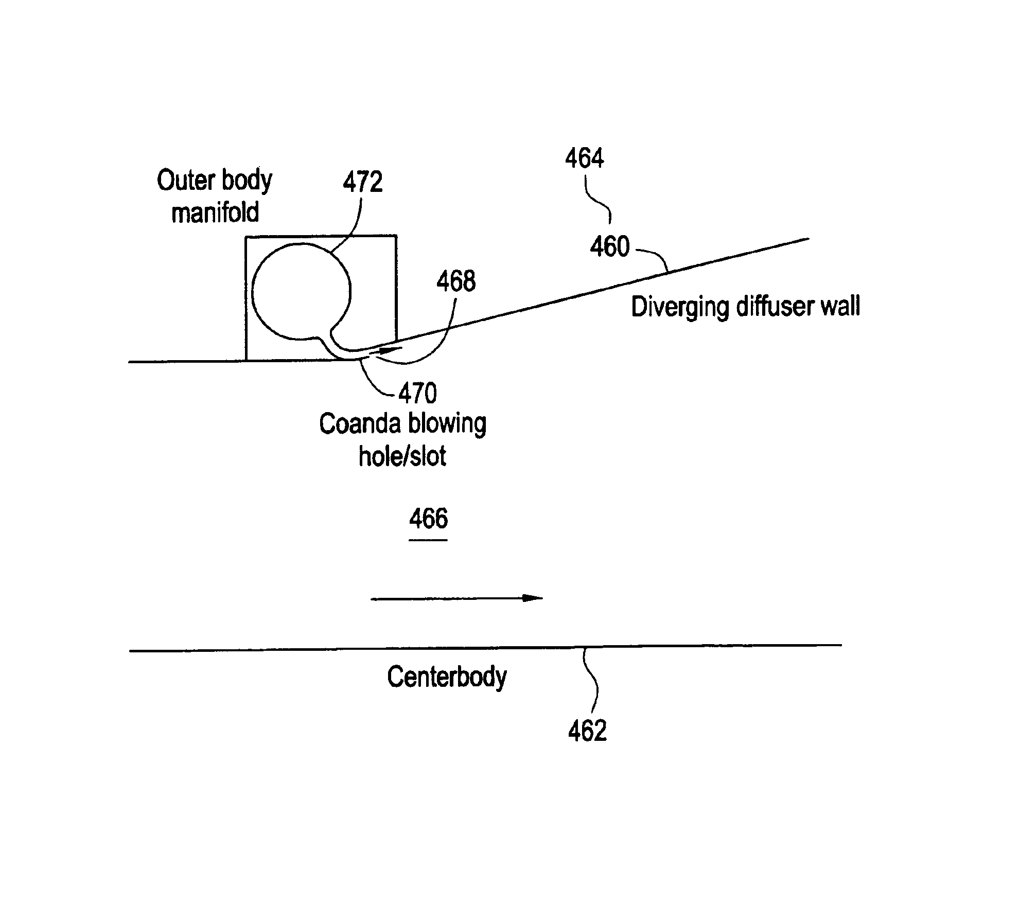
[0043]This design employs fluidic actuation to allow turbine diffusers to be designed with one or all of the following attributes: for a given value of area ratio, design shorter diffusers to reduce cost and minimize turbine length; for a given value of diffuser length, increase the expansion angle (area ratio) to improve diffuser performance and increase turbine efficiency; retrofit fluidic actuators to existing diffusers that have separated flow to improve performance at all operating conditions (e.g. full load and part load).

[0044]By applying fluidic actuation to a separated diffuser flow, it is shown below that exhaust diffuser pressure recovery can be significantly improved at different operating conditions.

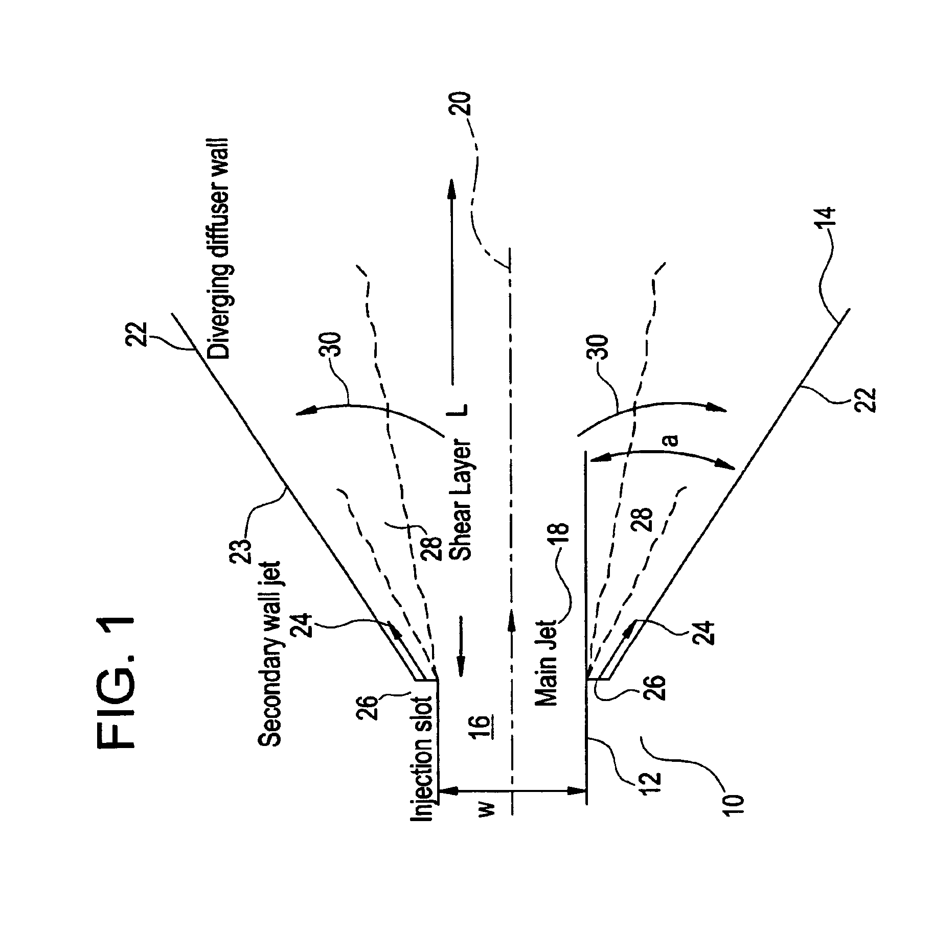
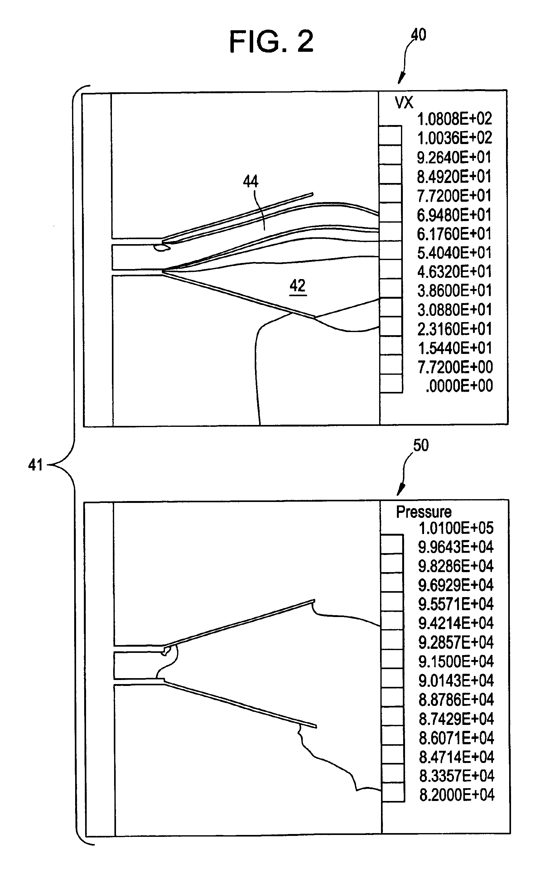
[0045]A description of a fluidic actuating scheme, designed to improve diffuser performance, may be given in reference to an idealized two-dimensional diffuser geometry. Results of numerical flow simulations are discussed below. For the cases studied, the main diffuser flow ...


PUM


Abstract

A diffuser includes an opening along the diffuser wall for preventing or delaying boundary layer separation of the main flow. The opening may include a curved passageway having a curvature convex relative to the main flow for utilizing the Coanda effect. A gas turbine may include the diffuser with an opening and a centerbody with an opening, each for providing a secondary flow of fluid into the diffuser. The gas turbine may direct fluid from an upstream turbine stage to the opening. A steam turbine may include the diffuser and may situate the opening downstream the diffuser inlet but upstream the location of boundary separation.

Description

BACKGROUND OF THE INVENTION[0001]This invention generally relates to a fluidic actuating scheme, and more particularly, this invention relates to fluidic actuation for improved diffuser performance.[0002]Typically, the maximum outlet to inlet area ratio of a gas turbine exhaust diffuser (and therefore the amount of effective flow diffusion following the last turbine stage) is constrained by flow separation issues and / or allowable axial diffuser length. Diffuser will exhibit separated flow if the expansion is too rapid (large diffuser angle) or the diffuser area ratio is too large.[0003]For a given diffuser length, the area ratio is determined by the diffuser expansion angle. The maximum included angle, which can be tolerated before significant flow separation occurs, is generally of the order of 10 degrees. For diffusers that are not limited in length, the maximum area ratio that can be tolerated before significant separation occurs is generally of the order of 2.4 (outlet area divi...

Claims


Application Information

Patent Timeline
Patent Type & Authority Patents(United States)
IPC IPC(8): F01D25/30F01D17/00F01D25/00F01D17/10F04F5/54F04F5/00F02C7/04F15D1/06
CPCF01D25/305F04F5/54F15D1/06Y10S415/914F05D2250/324F01D25/30
Inventor GRAZIOSI, PAOLOWARREN, JR., RICHARD EDWINFRIC, THOMAS FRANKMANI, RAMANIHOFER, DOUGLAS CARL
Owner GENERAL ELECTRIC CO
Why Eureka
Try Eureka