Position information estimation device, method thereof, and program

a position information and estimation device technology, applied in direction finders using radio waves, multi-channel direction-finding systems using radio waves, instruments, etc., can solve problems such as scaling problems, arbitrariness in the sequence and magnitude of separated signals, and difficulty in accommodation for a mixture of three or more signals, so as to avoid the influence of scaling ambiguity and reduce the amount of calculation

Inactive Publication Date: 2006-05-02
NIPPON TELEGRAPH & TELEPHONE CORP
View PDF9 Cites 14 Cited by
  • Summary
  • Abstract
  • Description
  • Claims
  • Application Information

AI Technical Summary

Benefits of technology

[0035]What is required for the calculation is the calculation according to formulae which are expressed in terms of the ratio of elements in the matrix, and the amount of calculation can be reduced than when determining the directivity pattern of a separated signal and searching for a minimum location angle thereof. Using the ratio of elements avoids the influence of the scaling ambiguity.

Problems solved by technology

However, it should be noted that the independent component analysis is based only on the independence of signals, and accordingly there remains arbitrariness as regards the sequence and the magnitude of the separated signals.
As will be described later, the arbitrariness of the sequence leads to a permutation problem and the arbitrariness of the magnitude leads to a scaling problem.
However, with this ICA method, accommodation for a mixture of three or more signals involves difficulties which will be described later.
In addition, the determination of a minimum gain of the directivity pattern requires a high computational cost calculations.
In this instance, the ICA can take place in the similar manner as before with a 3×3 separation matrix, but the analysis of the gain of a directivity pattern involves difficulties.
However, it is not always assured that the two rows suppress the signal in the same direction.
As a consequence, it is contemplated that the application of the prior art incorporating the ICA method to a situation involving three or more signals is difficult to achieve.
What matters during the blind signal separation in the frequency domain relates to a permutation problem and a scaling problem.
This method of solving the permutation problem requires a high computational cost in determining minimum gains of directivity patterns as mentioned previously, and in addition, where the number I of signal sources is equal to or greater than 3, a trial-and-error of appropriately rearranging W(ω)'s for all frequencies is necessary.

Method used


Image

  • Position information estimation device, method thereof, and program
  • Position information estimation device, method thereof, and program
  • Position information estimation device, method thereof, and program

Examples


first embodiment

[0073]In this first embodiment, the direction of a signal source, or the arrival direction of a source signal which is radiated from the signal source is determined.

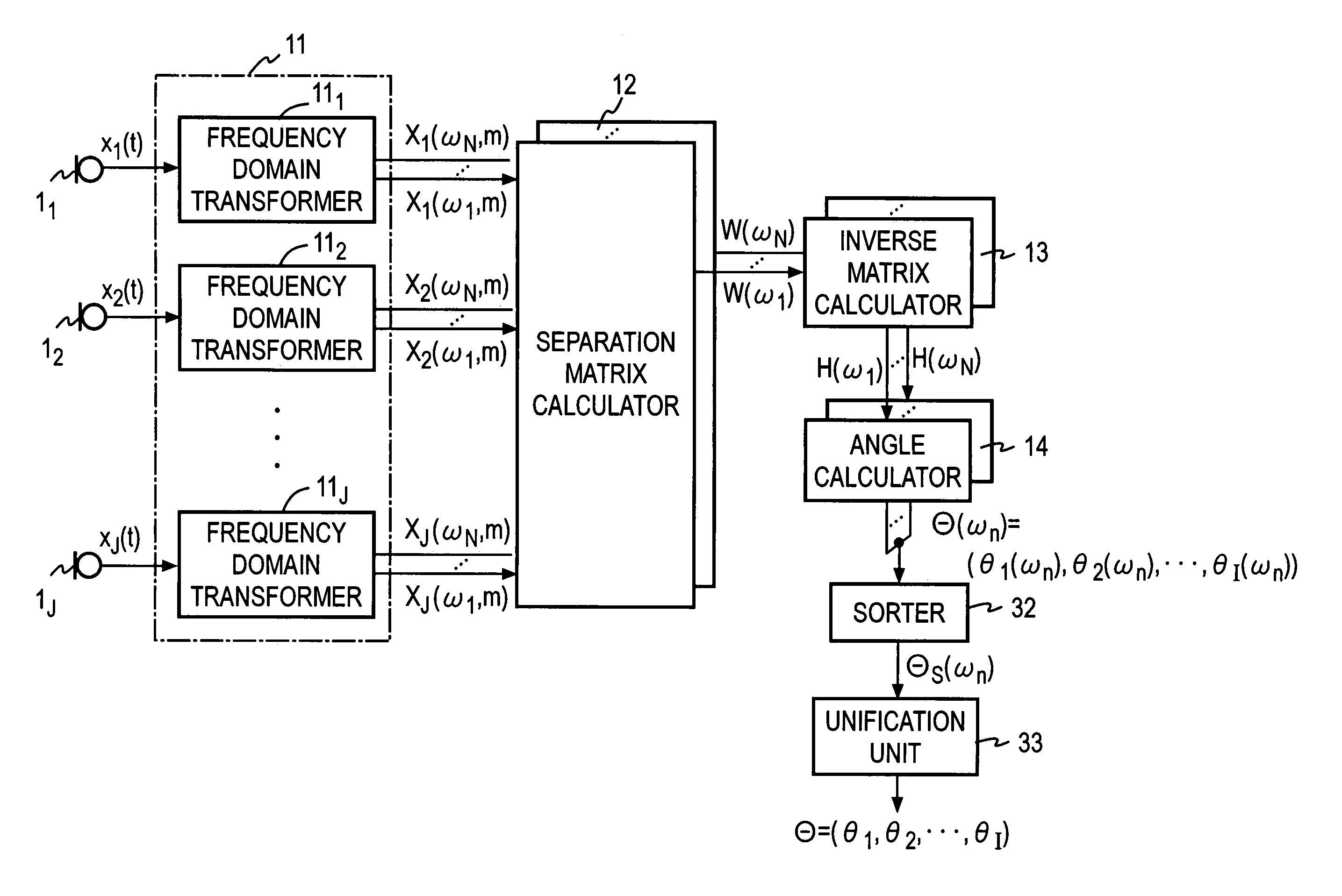
[0074]FIG. 5 shows a functional arrangement of the first embodiment, and FIG. 6 shows a flow chart of part of a processing procedure therefor.

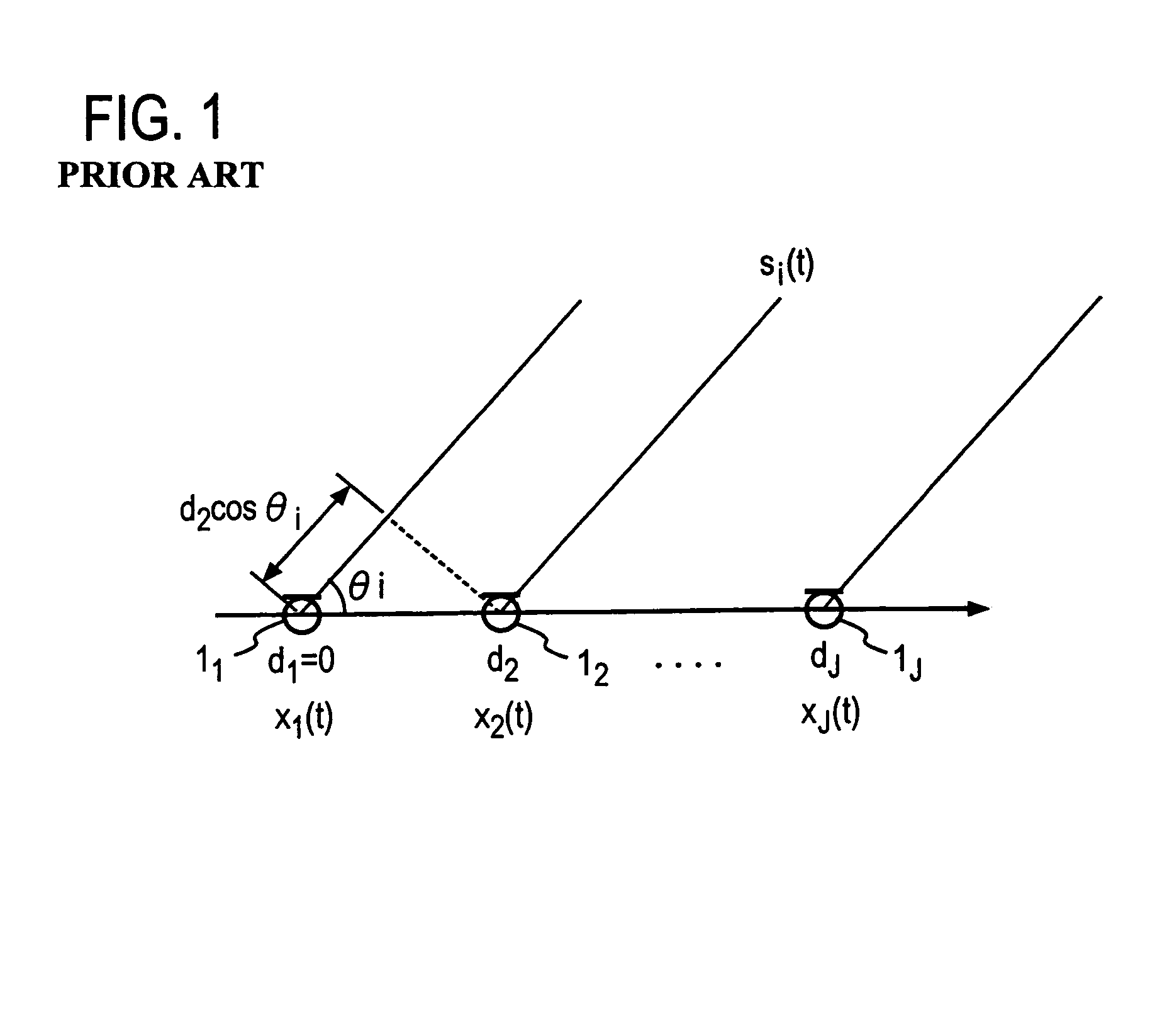
[0075]J sensors 11, 12, . . . , 1J, which are equal to or greater in number than the number I of signal sources, are disposed in an array as shown in FIG. 1. A spacing between adjacent sensors is normally equal to or less than one-half the shortest wavelength of source signals. Signals x1(t) which are observed by the sensors 1j (j=1, 2, . . . , J) are transformed into frequency domain signals Xj(ω, m) as by short-time Fourier transform in respective frequency domain transformers 11j (step S1, FIG. 6). Separation matrices W(ωn) (n=1, 2, . . . , N) for each angular frequency ωn for these frequency domain signals Xj(ω, m) are calculated through the independent component analysis proce...

second embodiment

[0095]A second embodiment is directed to obtaining direction information which is one item of positional information of signal sources. According to the second embodiment, at least three sensors which are disposed in at least two dimensions are used to allow a direction of a signal source to be estimated wherever the signal source is directed, thus allowing the permutation problem involved with the blind signal separation to be solved in a relatively simple manner. Specifically, a conical surface which is based on direction information is estimated, and a straight line which is in common to a plurality of conical surfaces is estimated to determine direction information.

[0096]A functional arrangement of the second embodiment as applied to the blind signal separation system is shown in FIG. 12, and a processing procedure used therein is shown in FIG. 13. By way of example, four sensors 11, 12, 13 and 14 are disposed on a circle at an equal interval, which is chosen to be equal to or l...

third embodiment

[0125]In a third embodiment, a curved surface on which a signal source exists is used as positional information which is based on the ratio of distances between a pair of sensors and a single signal source. In the first and the second embodiment, an assumption is made that signal sources are located remotely from sensors, and accordingly, signals from the signal sources are oncoming as plane waves to the sensors. However, when distances between signal sources and sensors are relatively short, a signal is oncoming as a spherical wave to a sensor. In view of this, when a ratio Aji(ω) / Aj′i(ω) of elements of a mixing matrix A(ω) is interpreted according to a spherical wave (close distance field) model, information other than the direction of a signal source i can be estimated.

[0126]Specifically, using a close distance field model, a frequency response Aji(ω) can be expressed as follows:

Aji(ω)=(1 / ∥qi−dj∥)exp(jωc−1(∥qi−dj∥))

where qi is a vector indicating the position of a signal source i...


PUM


Abstract

Signals from a plurality of sources are observed by a plurality of sensors disposed in two dimensions, and the observed signals are subject to a short-time Fourier transform, from which frequency domain signals are derived. Using the independent component analysis process on the frequency domain signals, separation matrices are produced, and an inverse matrix of each separation matrix is calculated. The direction of each source is calculated based on a ratio of a pair of elements in each column of the inverse matrix.

Description

TECHNICAL FIELD[0001]The present invention relates to an apparatus, a method and a program for estimation of positional information of each of a plurality of signal sources such as sound sources and radio wave sources on the basis of observation with a plurality of sensors of signals which are radiated from the signal sources and then mixed together, or more specifically, for estimation of information containing at least one of parameters which indicate the position to be used in the detection of arrival directions of signals and in the separation of signals into each signal source as well as in the recovery of signals.BACKGROUND ART[0002]The use of the independent component analysis (hereafter abbreviated as ICA) has been proposed to estimate arrival directions of source signals and to separate source signals from oncoming signals observed by a plurality of sensors when signals from a plurality of signal sources are mixed in the space before they reach the sensors. Mixing in the sp...

Claims


Application Information

Patent Timeline
Patent Type & Authority Patents(United States)
IPC IPC(8): G01C9/00G01S3/46G01S3/74G01S3/80G01S3/808
CPCG01S3/46G01S3/74G01S3/808G01S3/8006
Inventor SAWADA, HIROSHIMUKAI, RYOARAKI, SHOKOMAKINO, SHOJI
Owner NIPPON TELEGRAPH & TELEPHONE CORP
Why Eureka
Try Eureka