Connector

a technology of connecting rods and connectors, applied in the direction of coupling devices, two-part coupling devices, electrical devices, etc., can solve the problems of easy introduction of skew, difficult to perform impedance matching between, and patent document 1 is not disclosed, so as to achieve the effect of suppressing skew

Active Publication Date: 2016-06-14
JAPAN AVIATION ELECTRONICS IND LTD
View PDF17 Cites 4 Cited by
  • Summary
  • Abstract
  • Description
  • Claims
  • Application Information

AI Technical Summary

Benefits of technology

[0005]It is an object of the present invention to provide a connector which can suppress skew between contacts which constitute one differential pair.

Problems solved by technology

In addition, Patent Document 1 dose not disclose which is a signal contact among the contacts.
Thus, in the connector 101 of Patent document 1, if any two of the contacts constitute one differential pair, it is difficult to perform impedance matching therebetween.
Accordingly, the connector 101 of the Patent Document 1 has a problem that skew is easily introduced.

Method used


Image

  • Connector
  • Connector
  • Connector

Examples


Embodiment Construction

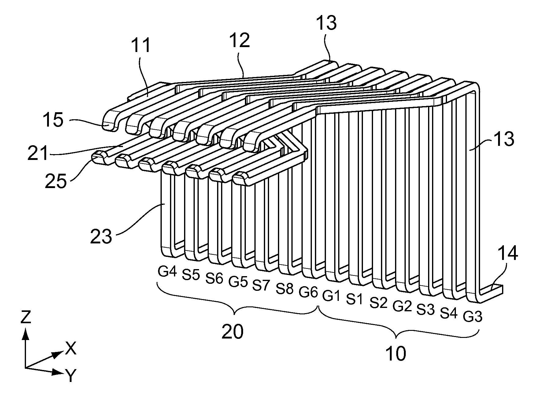
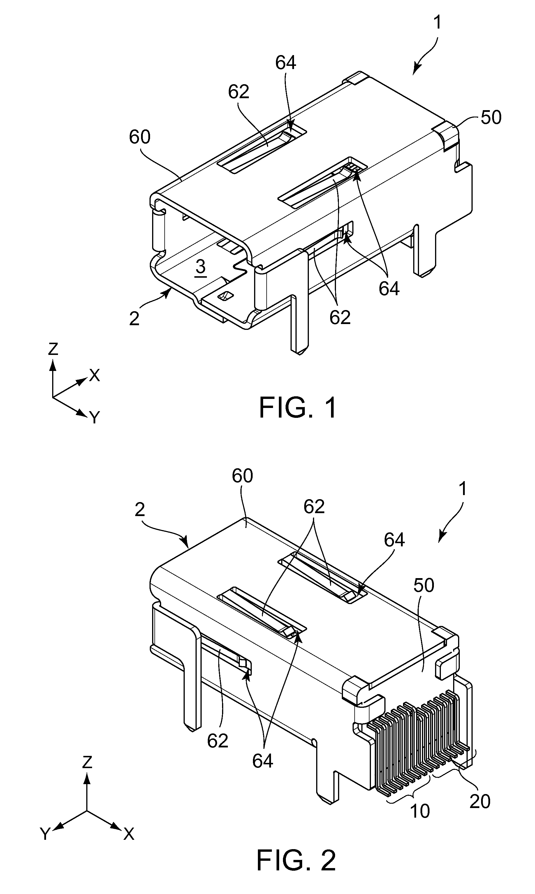
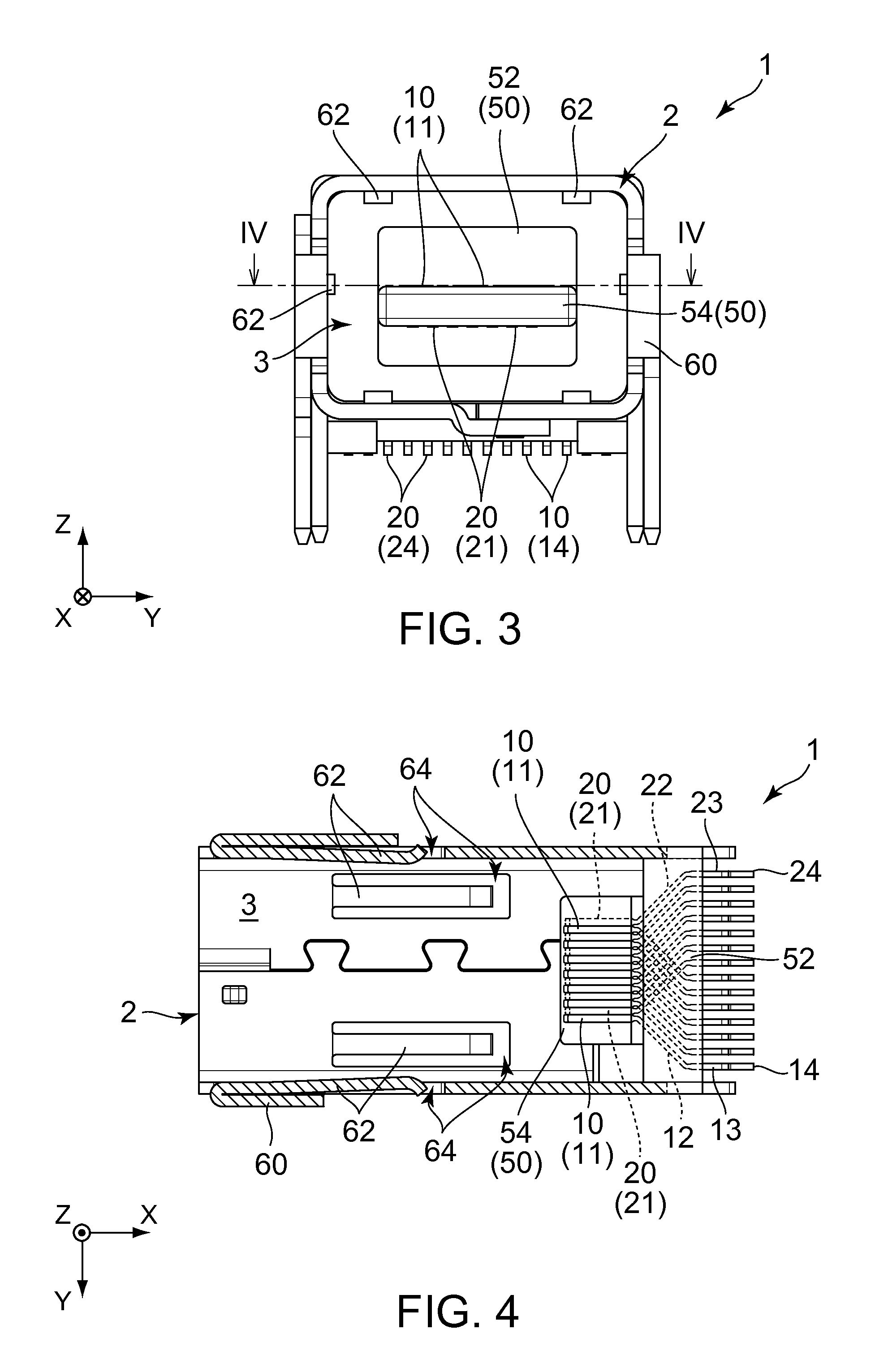
[0032]With reference to FIGS. 1 to 4, a connector 1 according to an embodiment of the present invention is mounted and fixed to on an object such as a circuit board (not shown) when used. The connector 1 comprises a plurality of first contacts (contacts) 10, a plurality of second contacts (contacts), a housing 50 and a shell 60. Each of the first contacts 10 is made of conductor. Each of the second contacts 20 is made of conductor. The housing 50 is made of insulator. The shell 60 is made of metal. The connector 1 according to the present embodiment is a receptacle having a receiving portion 3 which is opened at a mating end 2. A mating connector is a plug (not shown) which includes a plurality of mating contacts. The connector 1 according to the present embodiment receives a part of the plug (not shown) in the receiving portion 3, so that the connector 1 of receptacle according to the present embodiment is mated with the plug (not shown) along an X-direction (mating direction).

[003...


PUM


Abstract

A connector is mateable with a mating connector along a mating direction. The mating connector includes a plurality of mating contacts. The connector comprising a plurality of contacts which are held by a housing. Each of the contacts has a contact portion, a terminal portion and an intersecting portion. The terminal portion is positioned at a position different from a position of the contact portion in a pitch direction perpendicular to the mating direction. The intersecting portion is positioned between the contact portion and the terminal portion. The intersecting portions intersect both the mating direction and the pitch direction in a plane which is defined by the mating direction and the pitch direction. The contacts include at least a plurality of first contacts and a plurality of second contacts. The contact portions of the second contacts are positioned apart from the contact portions of the first contacts in a predetermined direction perpendicular to both the mating direction and the pitch direction. The first contacts include signal contacts which constitute at least one differential pair. The signal contacts of the differential pair have shapes same as each other.

Description

CROSS REFERENCE TO RELATED APPLICATIONS[0001]An applicant claims priority under 35 U.S.C. §119 of Japanese Patent Application No. JP2014-032267 filed Feb. 21, 2014.BACKGROUND OF THE INVENTION[0002]This invention relates to a connector which comprises signal contacts constituting at least one differential pair for high-speed signal transmission.[0003]With reference to FIGS. 21 and 22, a connector 101 of JPA 2012-54215 (Patent Document 1) comprises a plurality of contacts, a housing 102 and a shell 103. The contacts are held by the housing 102. The housing 102 is covered by the shell 103. The contacts are divided into two groups. Contact portions 201 of the contacts of each group are arranged in one row in a pitch direction. In other words, the contact portions 201 of the contacts are arranged in two rows. On the other hand, terminal portions 202 of the contacts of the two groups are arranged in one row in the pitch direction. Specifically, the terminal portions 202 of the contacts of...

Claims


Application Information

Patent Timeline
Patent Type & Authority Patents(United States)
IPC IPC(8): H01R24/60H01R13/6471H01R12/72
CPCH01R24/60H01R13/6471H01R12/724
Inventor KAWAMURA, CHIKARATANAKA, YUKITAKA
Owner JAPAN AVIATION ELECTRONICS IND LTD
Why Eureka
Try Eureka