Intermediate two-dimensional scanning with a three-dimensional scanner to speed registration

a three-dimensional scanner and two-dimensional scanning technology, applied in the field of intermediate two, can solve the problems of increasing the cost of the scanning project, difficult to remove the need for a user to carry out manual registration steps, and relatively time-consuming manual registration procedures

Active Publication Date: 2016-06-21
FARO TECH INC
View PDF1066 Cites 46 Cited by
  • Summary
  • Abstract
  • Description
  • Claims
  • Application Information

AI Technical Summary

Problems solved by technology

Some registration procedures involve relatively time-consuming manual procedures such as identifying by a user each target and matching the targets obtained by the scanner in each of the different registration positions.
However, even with the simplifications provided by the methods of '352, it is today still difficult to remove the need for a user to carry out the manual registration steps as described above.
This adds to the cost of the scanning project.
Furthermore, the manual registration process sometimes reveals that the overlap between adjacent scans was insufficient to provide proper registration.
When such problems occur, the operator must return to the site to obtain additional scans.
In some cases, it is not possible to return to a site.
A building that was available for scanning at one time may be impossible to access at a later time.
A forensics scene of an automobile accident or a homicide is often not available for taking of scans for more than a short time after the incident.

Method used


Image

  • Intermediate two-dimensional scanning with a three-dimensional scanner to speed registration
  • Intermediate two-dimensional scanning with a three-dimensional scanner to speed registration
  • Intermediate two-dimensional scanning with a three-dimensional scanner to speed registration

Examples


Embodiment Construction

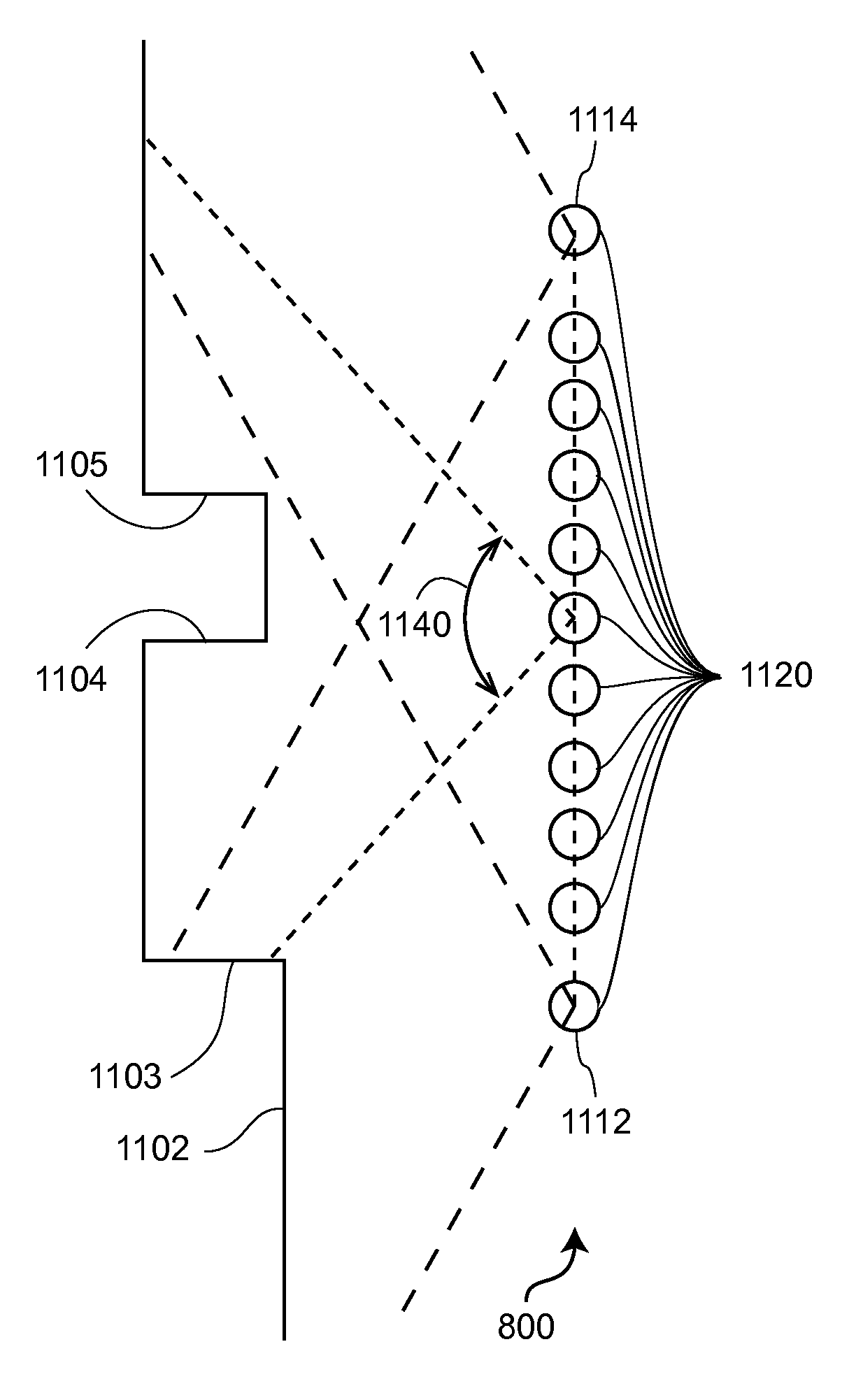
[0032]The present invention relates to a device that includes a 3D scanner used in two modes, a first mode in which 3D coordinates of an object surface are obtained over points over a 3D region of space and a second mode in which 3D coordinates of an object surface are collected along a horizontal plane, where the two modes of the 3D scanner are used together to provide automatic registration of 3D scans over a 3D region of space encompassing more than one scan of 3D regions of space.

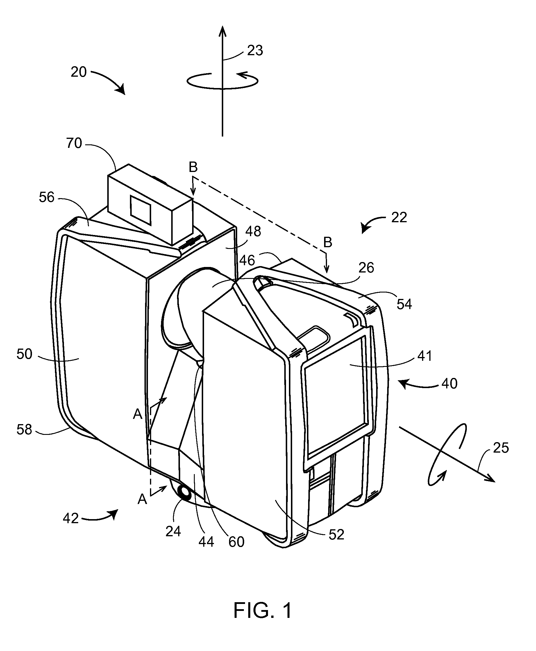
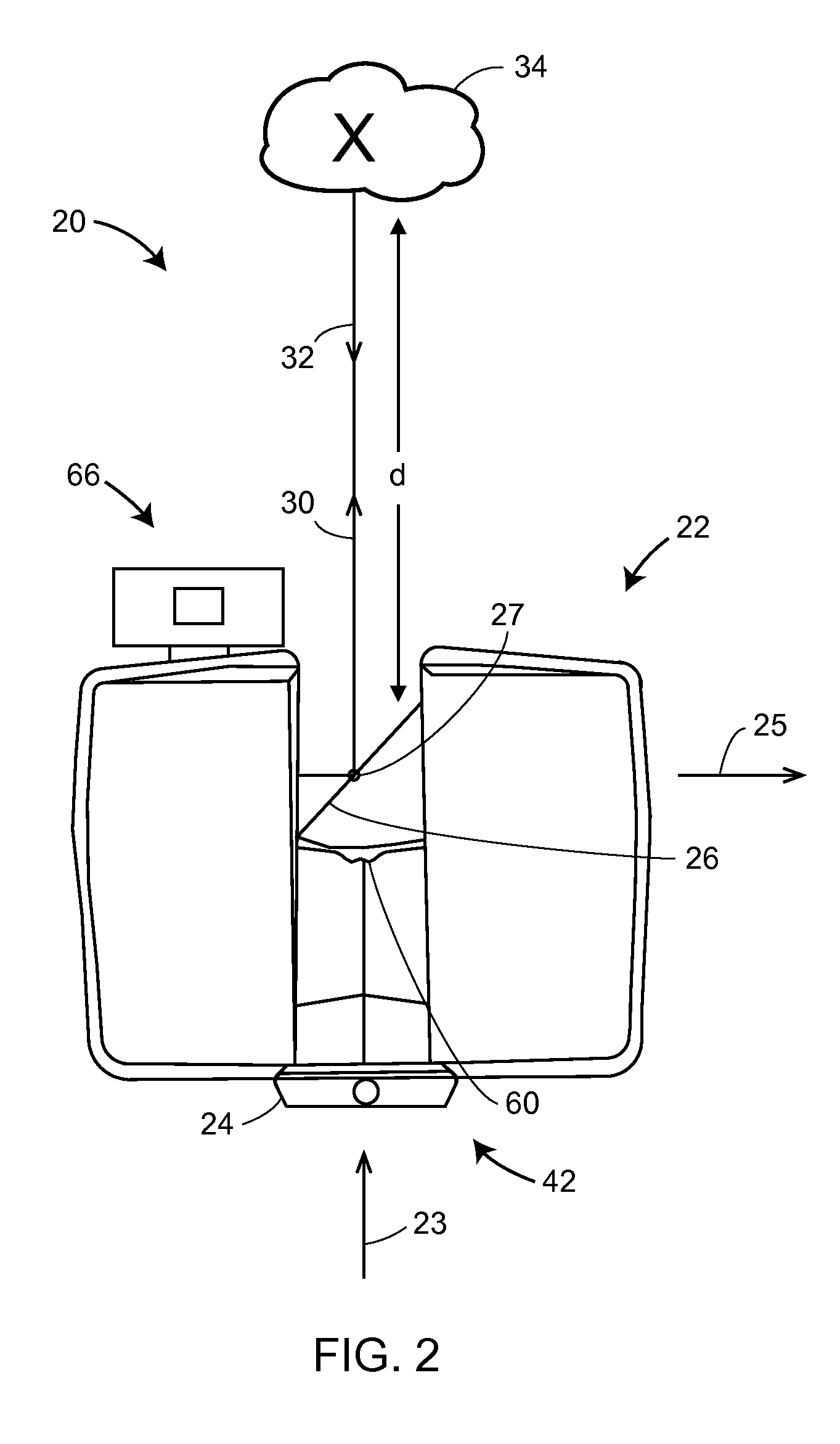
[0033]Referring now to FIGS. 1-3, a laser scanner 20 is shown for optically scanning and measuring the environment surrounding the laser scanner 20. The laser scanner 20 has a measuring head 22 and a base 24. The measuring head 22 is mounted on the base 24 such that the laser scanner 20 may be rotated about a vertical axis 23. In one embodiment, the measuring head 22 includes a gimbal point 27 that is a center of rotation about the vertical axis 23 and a horizontal axis 25. The measuring head 22 has a r...


PUM


Abstract

A method for measuring and registering 3D coordinates has a 3D scanner measure a first collection of 3D coordinates of points from a first registration position. The 3D scanner collects 2D scan sets as 3D measuring device moves from first to second registration positions. A processor determines first and second translation values and a first rotation value based on collected 2D scan sets. 3D scanner measures a second collection of 3D coordinates of points from second registration position. Processor adjusts the second collection of points relative to first collection of points based at least in part on first and second translation values and first rotation value. Processor identifies a correspondence among registration targets in first and second collection of 3D coordinates, and uses this correspondence to further adjust the relative position and orientation of first and second collection of 3D coordinates.

Description

CROSS-REFERENCE TO RELATED APPLICATIONS[0001]The present application claims the benefit of International Patent Application No. PCT / IB2013 / 003082, filed Sep. 27, 2013, which claims the benefit of German Patent Application No. 10 2012 109 481.0, filed Oct. 5, 2012 and of U.S. Patent Application No. 61 / 716,845, filed Oct. 22, 2012, the contents of all of which are incorporated by reference herein.BACKGROUND OF THE INVENTION[0002]U.S. Pat. No. 8,705,016 ('016) describes a laser scanner which, through use of a rotatable mirror, emits a light beam into its environment to generate a three-dimensional (3D) scan. The contents of this patent are incorporated herein by reference.[0003]The subject matter disclosed herein relates to use of a 3D laser scanner time-of-flight (TOF) coordinate measurement device. A 3D laser scanner of this type steers a beam of light to a non-cooperative target such as a diffusely scattering surface of an object. A distance meter in the device measures a distance t...

Claims


Application Information

Patent Timeline
Patent Type & Authority Patents(United States)
IPC IPC(8): G01B11/24G01B11/27G01B11/00G09B29/00G05D1/02G01S7/481G01S7/00G01S17/89G01S17/88B25J13/08G01S17/42G01S17/36G01C15/00G01S7/48G01S17/02G01S17/87G01C7/04G01S17/86
CPCG09B29/004G01S17/42G01S17/89G01S7/003G01S7/4813G05D1/0274B25J13/08G01S17/88G01B11/002G01B11/272G01S7/4817G01S17/36G01C15/002G05D1/024G01S7/4808G01S17/023G01S17/87G05D2201/0207G01C7/04G01S17/86G06T2207/10016G01S17/48
Inventor ZWEIGLE, OLIVERBECKER, BERND-DIETMARBECKER, REINHARD
Owner FARO TECH INC
Why Eureka
Try Eureka