
Image processing device and method

a technology of image processing and processing device, applied in the field of image processing device and method, can solve the problems of inability to obtain stable images and inability to obtain solutions with stable precision

Active Publication Date: 2007-10-11
KK TOPCON
View PDF11 Cites 45 Cited by
  • Summary
  • Abstract
  • Description
  • Claims
  • Application Information

AI Technical Summary

Benefits of technology

[0009] Here, referring to the term “a relatively moving object”, typically the object is photographed when either one of the object or the photographing device is mobile while the other is stationary during photographing, but it may be photographed when both are mobile. That is, both may be mobile relative to each other during photographing. With four or more images having an overlapping area with each other, two pairs of stereo images can be selected. The number of images having an overlapping area is desired to be larger to improve the measurement precision of coordinates, preferably 10 or more, more preferably 50 or more, for example. The term “series of sequentially photographed images” refers to photographed images acquired sequentially over time, which may be images extracted from frames of moving images captured continuously with a video camera, or images photographed sequentially at appropriate time intervals with a still camera. Such images may be acquired from all the frames, or from every several frames, of moving images. The feature points are tracked sequentially as follows. For a feature point in a first image, a corresponding point is searched for in a second image, and when found, correlated to the feature point in the first image; then for the corresponding point in the second image now as a new feature point, a corresponding point is searched for in a third image, and when found, correlated to the feature point in the second image; etc. Here, feature points in a series of photographed images that are correlated with each other are referred to as “corresponding feature points”. The feature points appear newly, disappear and reappear over time, so at least three of the series of photographed images need to have their feature points correlated to each other. Stereo images are preferably selected from corrected images, which are the series of photographed images in which the position, magnification and tilt are corrected by reflecting the corresponding feature points, but also may be selected from the images as originally acquired as they can be correlated with each other in the orientation process and 3D measurement. The term “orientation” refers to a process for calculating the photographing position and tilt of the photographing device, and the term “3D measurement” refers to a process for calculating the 3D coordinates of each feature point. The term “images selectable as stereo images” refers to stereo images suitable for 3D measurements, for example images approximately equal in distance from the object or in magnification of the photographed images as well as approximately equal in photographing direction.
[0028] The present invention can provide an image processing device and method that can precisely measure the photographing position or posture of a photographing device or the coordinates of an object based on sequentially changing photographed images, such as moving images.

Problems solved by technology

When the photographing device is actually mounted on a moving body such as a car or held in a hand of a person for photographing, however, stable images cannot always be obtained because of the sway of the car or the person, twists and turns of the road, or bumps and potholes on the road surface.
A problem has been found with the calculation, however, that solutions with stable precision cannot be easily obtained if the photographing distance (magnification), photographing direction or baseline length of the stereo images changes.

Method used


Image

  • Image processing device and method
  • Image processing device and method
  • Image processing device and method

Examples


first embodiment

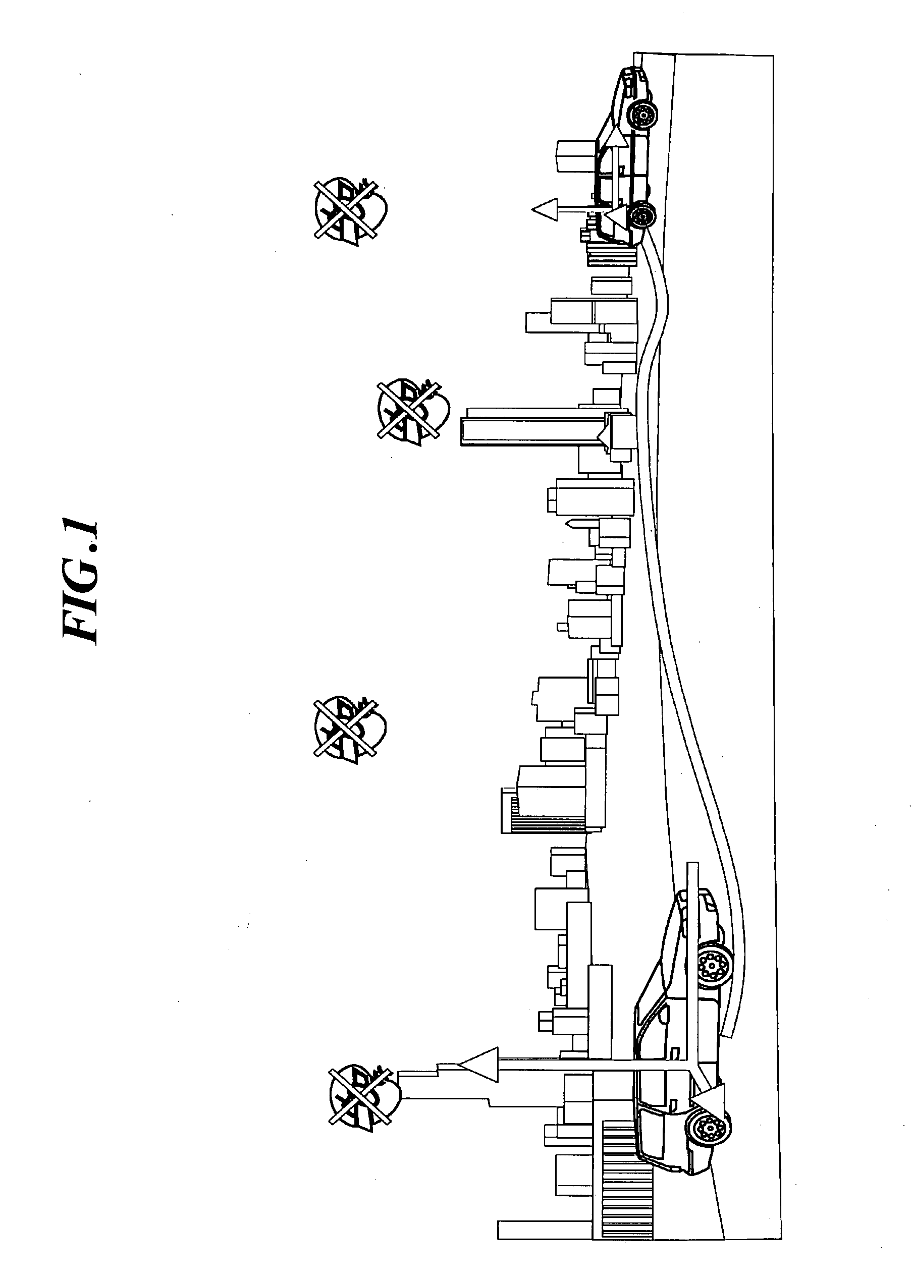
[0046]FIG. 1 is a view for explaining the concept of this embodiment. In this example, a camera is mounted on a car to photograph the scene of a street as an object over time, or while gradually changing the position of the car, and the positional coordinates of the camera, or the tracks of the car, are obtained from the results of tracking using the plurality of photographed images. This technique enables car navigation systems to continuously display the position of the car, and more importantly complements such systems in areas where GPS radio waves cannot be received. In the embodiment described below, images photographed during drastic motion are removed as inappropriate for use to obtain the positional coordinates of the camera.

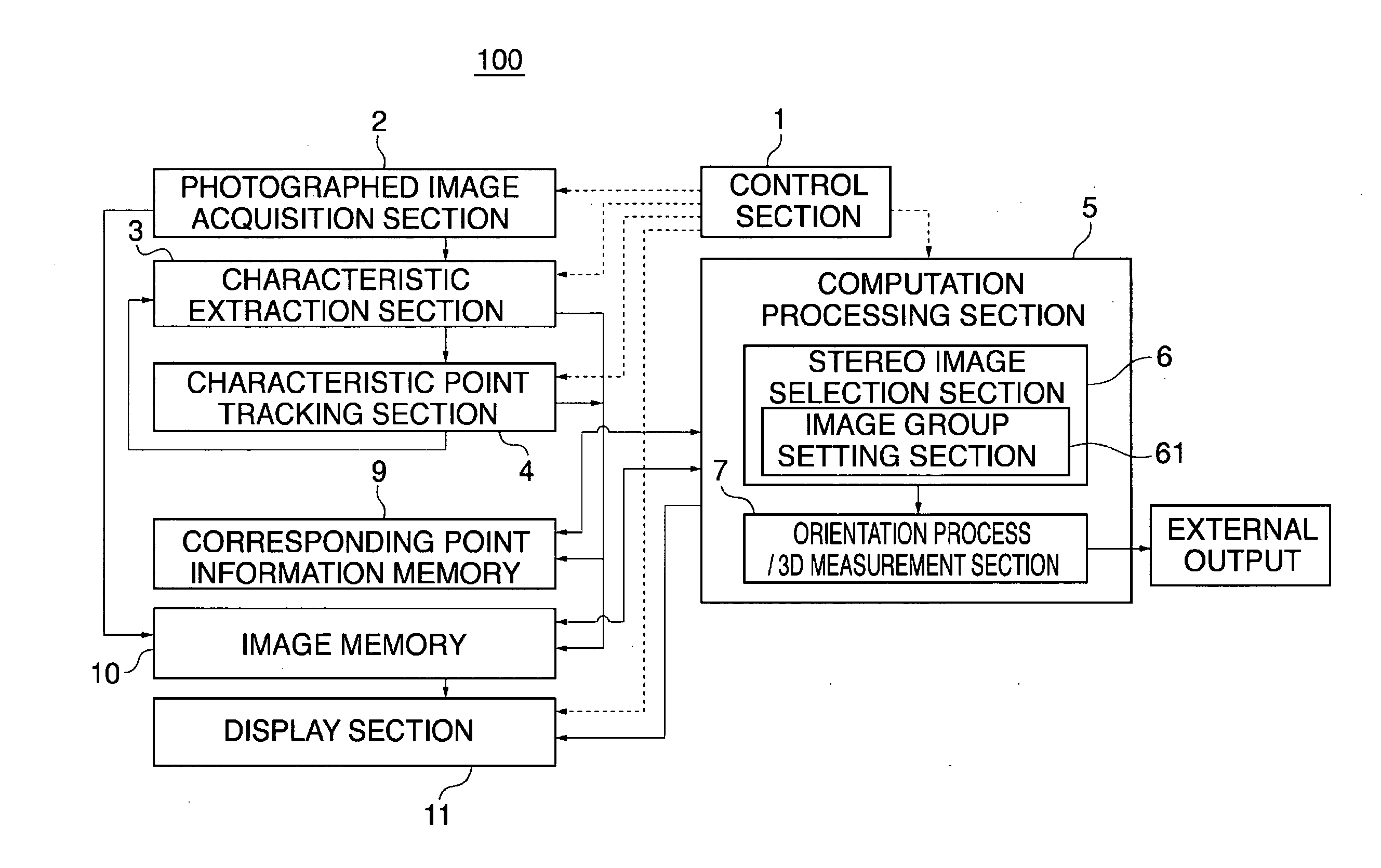
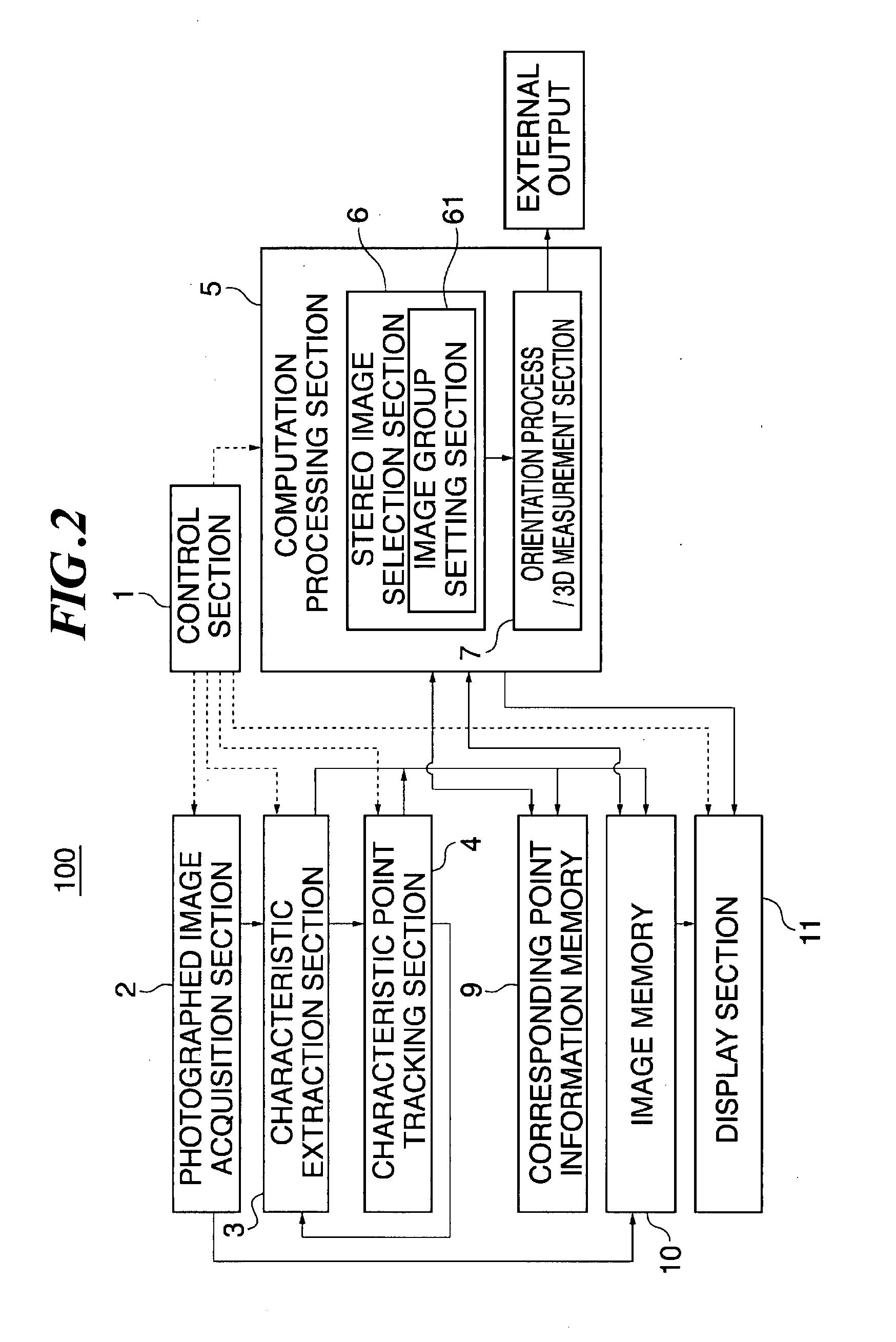
[0047]FIG. 2 shows an exemplary configuration of an image processing device 100 in this embodiment. In the drawing, reference numeral 1 denotes a control section for controlling respective sections of the image processing device 100 to enable it to fun...

second embodiment

[0096] In the first embodiment, the image group setting section groups photographed images according to the distance from the object to the photographing position, and the stereo image selection section selects stereo images from the group of images determined as belonging to one group, and specifies images photographed while the photographing position from the object to the photographing position, etc., is changing greatly, so that stereo images will not be selected from such images. In this embodiment, the image group setting section groups photographed images according to the distance from the object to the photographing position, or magnification, and the stereo image selection section selects stereo images from the group of images determined as belonging to one group. Images photographed while the photographing position is changing greatly are not actively removed. However, photographed images approximately equal in distance to the photographing position are grouped, so that st...

third embodiment

[0097] In the first embodiment, the image group setting section groups photographed images according to the distance from the object to the photographing position, and the stereo image selection section selects stereo images from the group of images determined as belonging to one group, and specifies images photographed while the photographing position from the object to the photographing position, etc., is changing greatly, so that stereo images will not be selected from such images. In this embodiment, the stereo image selection section specifies images photographed while the photographing position is changing greatly, so that stereo images will not be selected from such images. In this case, the photographed images are not grouped. However, unstable images photographed while the photographing position is changing greatly are removed before stereo images are selected. Thus, stereo images will not be selected from such inappropriate images. This embodiment is otherwise similar to t...


PUM


Abstract

An image processing device is provided that can precisely measure the photographing position or posture of a photographing device or the coordinates of an object based on sequentially changing photographed images. A series of sequentially photographed images are acquired, from which feature points are extracted. The feature points are tracked and correlated. Stereo images are selected from the series of photographed images correlated. Images selectable as stereo images are grouped into a group of images, from which stereo images are selected, before an orientation and a 3D measurement are performed. The images are grouped according to the distance from the object to the photographing position or the photographing magnification. Images with abrupt changes are removed so as to improve the measurement precision.

Description

BACKGROUND OF THE INVENTION [0001] 1. Technical Field [0002] The present invention relates to an image processing device and method. More particularly, the present invention relates to an image processing device and method for measuring the coordinates of a photographing device or an object by keeping track of a dynamic image of the object taken when the photographing device moves relative to the object. [0003] 2. Related Art [0004] There is known a technique to measure the position of a photographing device by continuously photographing an object while the photographing device is moving relative to the object. When the photographing device is actually mounted on a moving body such as a car or held in a hand of a person for photographing, however, stable images cannot always be obtained because of the sway of the car or the person, twists and turns of the road, or bumps and potholes on the road surface. Thus, it is necessary to correct vertical sway, magnification, direction and til...

Claims


Application Information

Patent Timeline
IPC IPC(8): H04N13/02
CPCG06T2207/30244G06T7/0044G06T7/74G01C11/06G01C21/005
Inventor ANAI, TETSUJIKOCHI, NOBUOOTANI, HITOSHI
Owner KK TOPCON
Learn More