Apparatus and method for optical 3D measurement

a technology of optical 3d and apparatus, applied in boring tools, dental prosthetics, dental tools, etc., can solve the problems of large overall height of the device, interference of light beams coming from various directions, etc., and achieve the effect of large scan area and easy comparison

Active Publication Date: 2009-11-12
SIRONA DENTAL SYSTEMS
View PDF13 Cites 43 Cited by
  • Summary
  • Abstract
  • Description
  • Claims
  • Application Information

AI Technical Summary

Benefits of technology

[0022]The first beam deflector is movable, unlike in prior devices, which have an immovably mounted beam deflector for deflecting the monitoring beam. The direction of the illuminating beam remains unchanged. The first beam deflector must thus be of small dimensions in order to deflect the monitoring beam. The overall height of the apparatus can consequently be lower than that of prior devices so that in dental applications, in particular, access to teeth inside an oral cavity is greatly facilitated.
[0068]Advantageously, the illuminating beam can consist of a series of component beams disposed in a plane. 3 D measurement can thus be carried out in parallel using the series of component beams so that the time taken for scanning is reduced.

Problems solved by technology

This means that the light beams coming from various directions can interfere only if the path lengths of the two light beams differ from each other by less than the coherence length.
A disadvantage of such devices is that a mirror or a prism is used for deflecting the projection beam or monitoring beam toward the object to be measured and for deflecting the reflected monitoring beam toward the image sensor, which is stationarily installed.
Therefore, in the case of a large scan area, the overall height of the devices is correspondingly large and is, in particular, a hindrance to 3 D measurement of teeth in the oral cavity of a patient.

Method used


Image

  • Apparatus and method for optical 3D measurement
  • Apparatus and method for optical 3D measurement
  • Apparatus and method for optical 3D measurement

Examples


Embodiment Construction

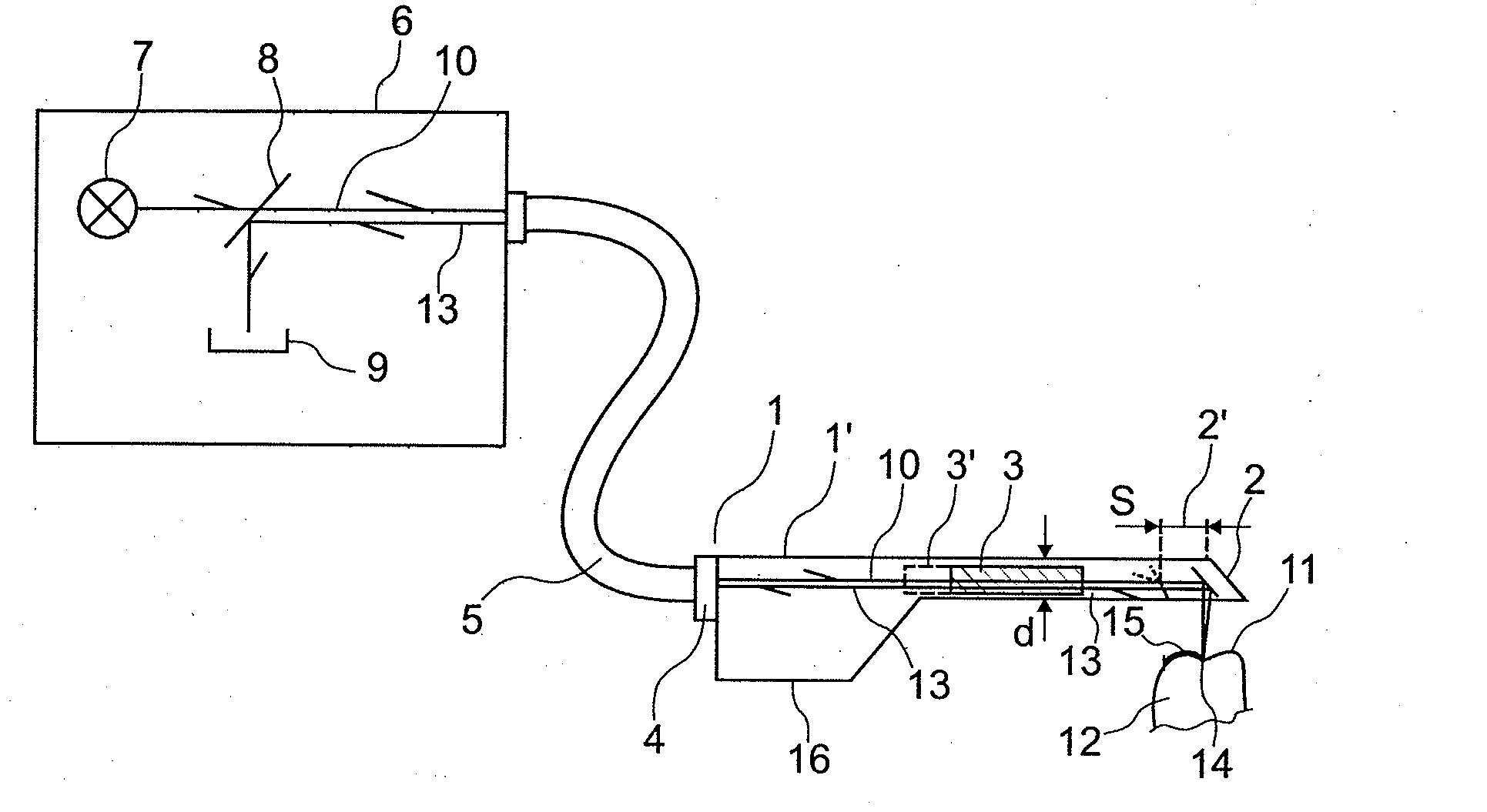
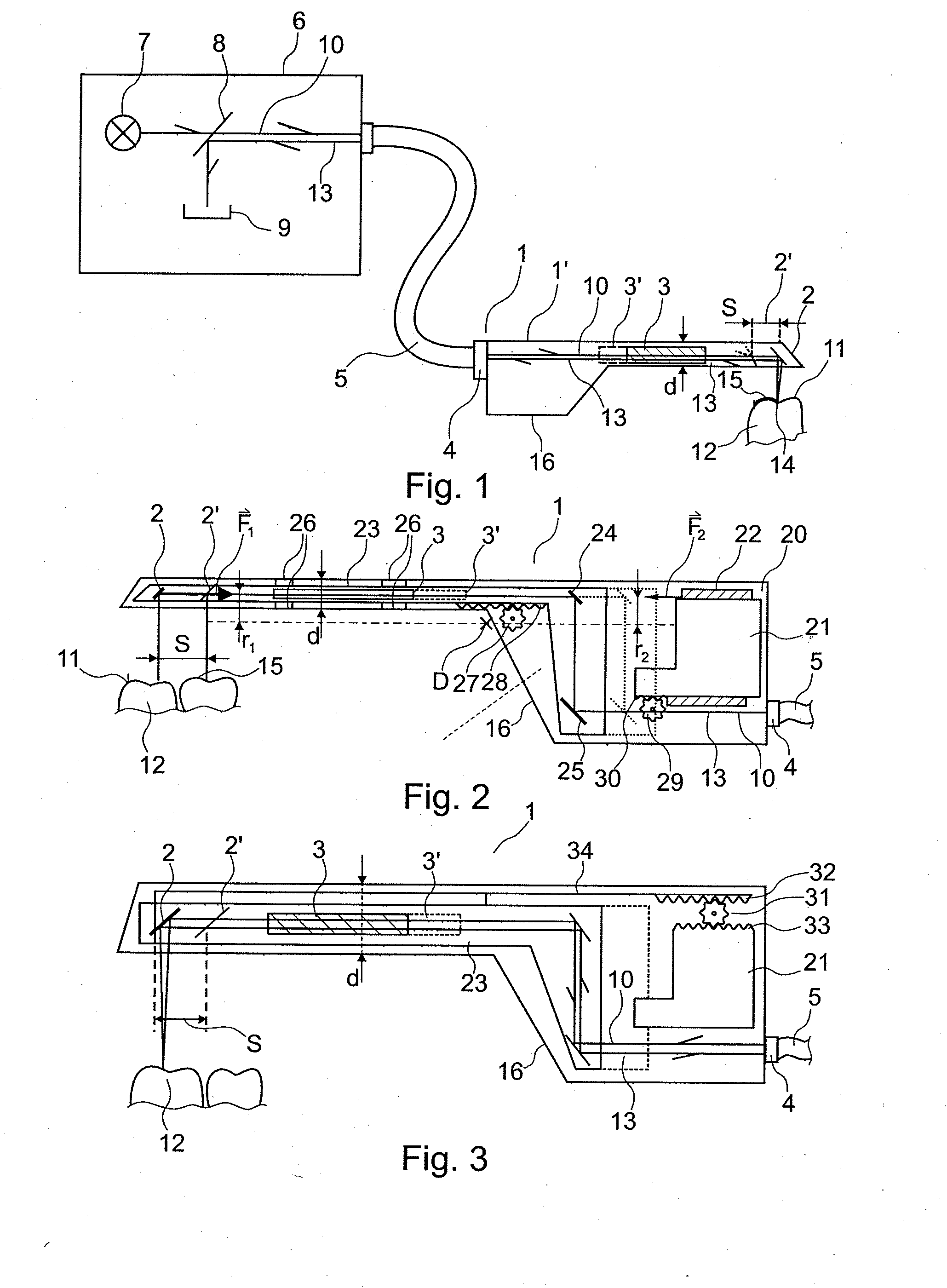
[0078]FIG. 1 shows an optical 3 D measuring apparatus 1 comprising a first beam deflector 2, an objective 3 and a connector 4 for a fiber-optic light guide 5. The first beam deflector 2 can be oscillated over a path distance S. The first beam deflector 2′, indicated by dashed lines, shows the position of the beam deflector 2 following linear movement thereof through the path distance S. The objective 3 is likewise moved together with the first beam deflector 2 linearly along the path S. The objective 3′, indicated by the dashed lines, shows the position of the objective 3 following movement thereof. The illustrated optical 3 D measuring apparatus 1 has the form of a dental handpiece that is connected to a base unit 6 by means of a fiber-optic light guide 5. The base unit 6 comprises a light source 7, a beam splitter 8, and an image sensor 9. A radiated light beam 10, which is generated by the light source 7, attenuated by the beam splitter 8 and guided by the fiber-optic light guide...


PUM


Abstract

The invention relates to an apparatus and a method for optical 3 D measurement, comprising a first beam deflector for deflecting an illuminating beam onto a measurement object and for deflecting the observation beam which is radiated back by the measurement object, wherein the first beam deflector can move along a path distance S.

Description

[0001]The present invention relates to an apparatus and method for optical 3 D measurement.PRIOR ART[0002]A number of devices for optical 3 D measurement are known in the prior art. In many cases, the optical 3 D measurement is carried out by optically scanning the surfaces of an object to be measured with the aid of one or more light beams. The surfaces can be scanned by means of a point light beam or one or more stripes of light.[0003]Devices are well-known in which linear scanning is carried out by using a stripe of light to scan the surface in a direction extending at right angles to the stripe of light.[0004]These devices often function on the basis of a chromatic confocal measuring method, a classical confocal measuring method with mechanical depth scan, a triangulation measuring method, a classical interferometry measuring method, a white-light interferometry measuring method, or a deflectometry measuring method.[0005]In the chromatic confocal measuring method, a polychromati...

Claims


Application Information

Patent Timeline
Patent Type & Authority Applications(United States)
IPC IPC(8): G01B11/24A61C19/04
CPCA61B5/0088G01B11/24A61C9/004A61B5/1077A61C9/0053A61B5/0068
Inventor THIEL, FRANKPFEIFFER, JOACHIMFORNOFF, PETER
Owner SIRONA DENTAL SYSTEMS
Why Eureka
Try Eureka