
Defect imaging method for lining Anti-corrosion pipeline

a technology of anti-corrosion pipeline and defect imaging, which is applied in the field of pipeline defect detection, can solve the problems of microscopic or macro changes in the lining anti-corrosion material layer, and achieve the effect of long-distance accurate detection, effective enhancement of signal amplitude, and improved signal-to-noise ratio

Inactive Publication Date: 2019-12-05
GUANGZHOU SPECIAL PRESSURE EQUIP INSPECTION & RES INST
View PDF0 Cites 4 Cited by
  • Summary
  • Abstract
  • Description
  • Claims
  • Application Information

AI Technical Summary

Benefits of technology

The present invention provides a method for detecting defects in a lining anti-corrosion pipeline. The method allows for visually and clearly showing the position and condition of the defects, making maintenance work easier. The use of ultrasonic guided waves and time reversal processing ensures accurate detection of defects in the pipeline. The imaging excitation signal is an ultrasonic signal that improves signal amplitude and reduces noise. Synchronous acquisition of the imaging excitation reflection and transmission signals improves data accuracy. The technical effect of the invention is to facilitate efficient and accurate detection of defects in lining anti-corrosion pipelines.

Problems solved by technology

As the anti-corrosion layer of the lining anti-corrosion pressure pipeline is directly in the environment of fluid, corrosion, mixture of various chemicals or the like, it is very likely to be corroded to cause defects, resulting in leakage.
When the lining anti-corrosion pressure pipeline has defects, some physical properties and chemical properties of the anti-corrosion material layer of the lining anti-corrosion pressure pipeline can change, thereby causing some microscopic or macroscopic changes in the lining anti-corrosion material layer.

Method used


Image

  • Defect imaging method for lining Anti-corrosion pipeline
  • Defect imaging method for lining Anti-corrosion pipeline
  • Defect imaging method for lining Anti-corrosion pipeline

Examples


Embodiment Construction

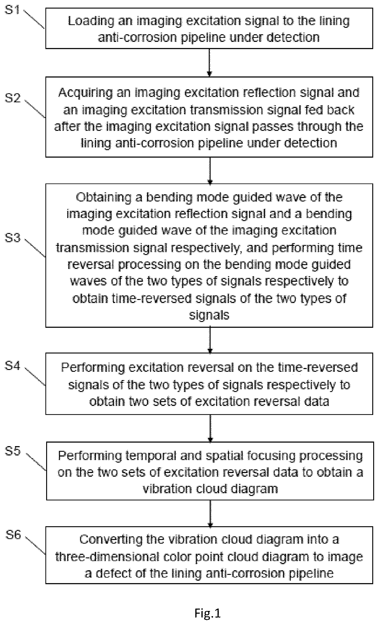
[0030]Refer to FIG. 1, which is a flow diagram of a defect imaging method for a lining anti-corrosion pipeline in embodiments of the present invention. The defect imaging method for a lining anti-corrosion pipeline includes the following steps:

[0031]Step S1: loading an imaging excitation signal to a lining anti-corrosion pipeline under detection.

[0032]In an embodiment, to image a defect of the lining anti-corrosion pipeline under detection, a first excitation transducer array and a second excitation transducer array are arranged at two ends in the axial direction of the lining anti-corrosion pipeline under detection respectively. Specifically, both the first excitation transducer array and the second excitation transducer array adopt piezoelectric ceramics based on the piezoelectric effect, and both are adhered to the surface of the lining anti-corrosion pipeline under detection through a couplant, to achieve vibration and electric signal conversion of the lining anti-corrosion pipe...


PUM


Abstract

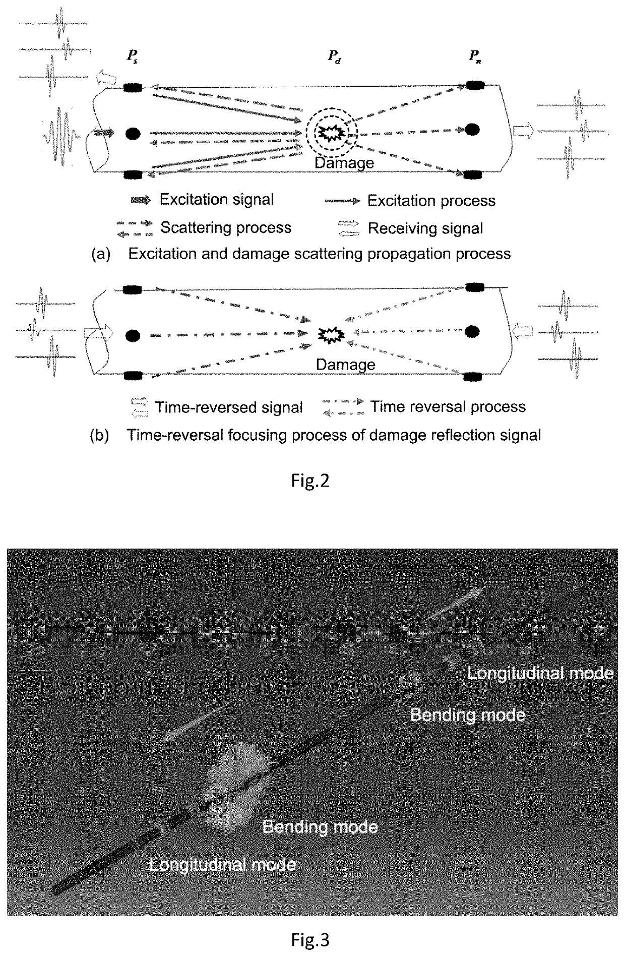
A defect imaging method for a lining anti-corrosion pipeline is provided, including following steps: loading an imaging excitation signal to the lining anti-corrosion pipeline under detection; acquiring an imaging excitation reflection signal and an imaging excitation transmission signal; obtaining bending mode guided waves of the imaging excitation reflection signal and the imaging excitation transmission signal respectively, and performing time reversal processing on the bending mode guided waves to obtain time-reversed signals; performing excitation reversal on the time-reversed signals to obtain excitation reversal data; performing temporal and spatial focusing processing on the excitation reversal data to obtain a vibration cloud diagram; and converting the vibration cloud diagram into a three-dimensional color point cloud diagram to image a defect of the lining anti-corrosion pipeline. By performing imaging processing, the defect position and condition can be obtained visually and clearly, thereby greatly facilitating subsequent maintenance work.

Description

CROSS-REFERENCE TO RELATED APPLICATIONS[0001]This application claims priority to Chinese Application No. CN 201810537009.4 having a filing date of May 30, 2018, the entire contents of which are hereby incorporated by reference.FIELD OF TECHNOLOGY[0002]The following relates to the field of pipeline defect detection, and in particular relates to a defect imaging method for a lining anti-corrosion pipeline.BACKGROUND[0003]The petrochemical industry is an important foundation and pillar industry of the national economy and plays a decisive role in the sustained and stable development of the national economy. In the petrochemical industry, anti-corrosion pressure pipelines are commonly used for oil and gas conveyance.[0004]The traditional anti-corrosion pressure pipeline mainly includes an outer anti-corrosion layer pressure pipeline and a lining anti-corrosion pressure pipeline. The outer anti-corrosion layer pressure pipeline is a pressure pipeline formed by providing an anti-corrosion...

Claims


Application Information

Patent Timeline
IPC IPC(8): G01N29/06G01N29/24G01N29/28F17D5/06
CPCG01N29/069F17D5/06G01N2291/269G01N2291/023G01N29/28G01N29/2437G01N29/043G01N29/52G01N2291/0258G01N2291/0425G01N2291/2634
Inventor LI, MAODONGYANG, BOZHAI, WEIHUANG, GUOJIALI, SHIPINGWANG, ZHIGANGLI, RONGGENZHONG, ZHIQIANG
Owner GUANGZHOU SPECIAL PRESSURE EQUIP INSPECTION & RES INST
Learn More